Toyota CH-R Service Manual: Dtc Check / Clear
DTC CHECK / CLEAR
CHECK DTCs (USING TECHSTREAM)
(a) Turn the ignition switch off.
(b) Connect the Techstream to the DLC3.
(c) Turn the ignition switch to ON.
(d) Turn the Techstream on.
(e) Enter the following menus: Chassis / EMPS / Trouble Codes.
Chassis > EMPS > Trouble Codes(f) Check the details of the DTCs.
Click here
.gif)
CHECK DTCs (USING SST CHECK WIRE)
(a) Using SST, connect terminals 13 (TC) and 4 (CG) of the DLC3.
SST: 09843-18040
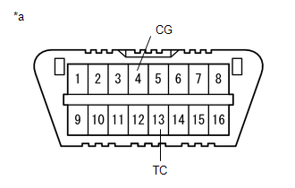
|
*a |
DLC3 |
(b) Turn the ignition switch to ON.
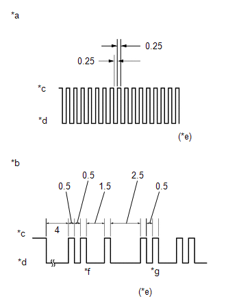
(c) Read and write down any DTCs indicated by the blinking of the EPS warning light in the combination meter assembly. Refer to the illustration to the right for examples of the normal system code and DTCs 21 and 22.
|
*a |
Normal System Code |
|
*b |
Codes 21 and 22 |
|
*c |
ON |
|
*d |
OFF |
|
*e |
Seconds |
|
*f |
Code 21 |
|
*g |
Code 22 |
HINT:
- If the EPS warning light does not blink to display stored DTCs or the
normal system code, inspect the circuit shown in the table below.
Trouble Area
Link
EPS warning light circuit
- If two or more malfunctions are detected simultaneously, DTCs will be displayed in ascending numerical order.
(d) Refer to Diagnostic Trouble Code Chart for DTC information.
Click here
(e) Check the details of the DTCs.
EPS DTC|
EPS Warning Light Display |
Tester Display |
|---|---|
|
11 |
C1511 |
|
C1512 |
|
|
C1513 |
|
|
C1514 |
|
|
C1517 |
|
|
12 |
C1528 |
|
13 |
C1541 |
|
15 |
C1515 |
|
16 |
C1516 |
|
22 |
C1552 |
|
23 |
C1554 |
|
24 |
C1521 |
|
C1522 |
|
|
C1523 |
|
|
25 |
C1531 |
|
C1532 |
|
|
C1533 |
|
|
C1534 |
|
|
C1551 |
|
|
C1555 |
|
|
26 |
C1581 |
|
C1582 |
|
|
41 |
U0100 |
|
42 |
U0129 |
|
44 |
C1567 |
|
45 (w/ Toyota Safety Sense P) |
U023A |
CLEAR DTCs (USING TECHSTREAM)
(a) Turn the ignition switch off.
(b) Connect the Techstream to the DLC3.
(c) Turn the ignition switch to ON.
(d) Turn the Techstream on.
(e) Enter the following menus: Chassis / EMPS / Trouble Codes.
Chassis > EMPS > Clear DTCs(f) Clear the DTCs.
Click here
(g) Turn the ignition switch off.
(h) Disconnect the Techstream from the DLC3.
 Terminals Of Ecu
TERMINALS OF ECU
CHECK POWER STEERING ECU ASSEMBLY
*a
Component without harness connected
(Power Steering ECU Assembly)
-
-
(a) Measure the ...
 Fail-safe Chart
FAIL-SAFE CHART
If a problem occurs in the power steering system, the power steering assist will
be stopped or the amount of power assist will be decreased to protect the system.
Power Steering Sy ...
Other materials:
Toyota CH-R Service Manual > Front Bumper: Components
COMPONENTS
ILLUSTRATION
*1
FRONT BUMPER ASSEMBLY
*2
FRONT FENDER MOULDING SUB-ASSEMBLY LH
*3
FRONT FENDER MOULDING SUB-ASSEMBLY RH
*4
RADIATOR COVER
ILLUSTRATION
*A
fo ...
Toyota CH-R Service Manual > Front Drive Shaft Assembly: Installation
INSTALLATION
CAUTION / NOTICE / HINT
HINT:
Use the same procedure for the RH side and LH side.
The following procedure is for the LH side.
PROCEDURE
1. INSTALL FRONT DRIVE INBOARD JOINT HOLE SNAP RING LH (for LH Side)
(a) Install a new front drive inboard joint hole snap ring ...
Toyota CH-R Owners Manual
- For safety and security
- Instrument cluster
- Operation of each component
- Driving
- Interior features
- Maintenance and care
- When trouble arises
- Vehicle specifications
- For owners
Toyota CH-R Service Manual
- Introduction
- Maintenance
- Audio / Video
- Cellular Communication
- Navigation / Multi Info Display
- Park Assist / Monitoring
- Brake (front)
- Brake (rear)
- Brake Control / Dynamic Control Systems
- Brake System (other)
- Parking Brake
- Axle And Differential
- Drive Shaft / Propeller Shaft
- K114 Cvt
- 3zr-fae Battery / Charging
- Networking
- Power Distribution
- Power Assist Systems
- Steering Column
- Steering Gear / Linkage
- Alignment / Handling Diagnosis
- Front Suspension
- Rear Suspension
- Tire / Wheel
- Tire Pressure Monitoring
- Door / Hatch
- Exterior Panels / Trim
- Horn
- Lighting (ext)
- Mirror (ext)
- Window / Glass
- Wiper / Washer
- Door Lock
- Heating / Air Conditioning
- Interior Panels / Trim
- Lighting (int)
- Meter / Gauge / Display
- Mirror (int)
- Power Outlets (int)
- Pre-collision
- Seat
- Seat Belt
- Supplemental Restraint Systems
- Theft Deterrent / Keyless Entry

0.0111