Toyota CH-R Service Manual: Radio Receiver Assembly Communication Stop Mode
DESCRIPTION
|
Detection Item |
Symptom |
Trouble Area |
|---|---|---|
|
Radio Receiver Assembly Communication Stop Mode |
Any of the following conditions are met:
|
|
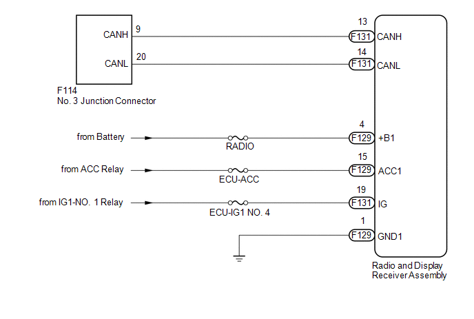
WIRING DIAGRAM

CAUTION / NOTICE / HINT
NOTICE:
- Because the order of diagnosis is important to allow correct diagnosis,
make sure to begin troubleshooting using How to Proceed with Troubleshooting
when CAN communication system related DTCs are output.
Click here
.gif)
- Before measuring the resistance of the CAN bus, turn the ignition switch off and leave the vehicle for 1 minute or more without operating the key or any switches, or opening or closing the doors. After that, disconnect the cable from the negative (-) battery terminal and leave the vehicle for 1 minute or more before measuring the resistance.
- After turning the ignition switch off, waiting time may be required
before disconnecting the cable from the negative (-) battery terminal. Therefore,
make sure to read the disconnecting the cable from the negative (-) battery
terminal notices before proceeding with work.
Click here
.gif)
- After performing repairs, perform the DTC check procedure and confirm
that the DTCs are not output again.
DTC check procedure: Turn the ignition switch ON and wait at least approximately 60 seconds.
- After the repair, perform the CAN bus check and check that all the ECUs
and sensors connected to the CAN communication system are displayed as normal.
Click here
.gif)
- The following may occur if a radio and display receiver assembly from
another vehicle is installed to this vehicle. Therefore, when replacing
the radio and display receiver assembly, be sure to replace it with a new
one.
- A communication malfunction DTC is stored.
- The radio and display receiver assembly does not operate normally.
- Inspect the fuses for circuits related to this system before performing the following procedure.
HINT:
- Before disconnecting related connectors for inspection, push in on each connector body to check that the connector is not loose or disconnected.
- When a connector is disconnected, check that the terminals and connector body are not cracked, deformed or corroded.
PROCEDURE
|
1. |
CHECK FOR OPEN IN CAN BUS LINES (RADIO AND DISPLAY RECEIVER ASSEMBLY BRANCH LINE) |
(a) Disconnect the cable from the negative (-) battery terminal.
(b) Disconnect the radio and display receiver assembly connector.
|
(c) Measure the resistance according to the value(s) in the table below. Standard Resistance:
|
|
| NG | .gif) |
REPAIR OR REPLACE CAN BRANCH LINES OR CONNECTOR (RADIO AND DISPLAY RECEIVER ASSEMBLY) |
|
|
2. |
CHECK HARNESS AND CONNECTOR (POWER SOURCE CIRCUIT) |
(a) Disconnect the radio and display receiver assembly connector.
|
(b) Measure the resistance according to the value(s) in the table below. Standard Resistance:
|
|
(c) Reconnect the cable to the negative (-) battery terminal.
(d) Measure the voltage according to the value(s) in the table below.
Standard Voltage:
|
Tester Connection |
Switch Condition |
Specified Condition |
|---|---|---|
|
F129-4 (+B1) - Body ground |
Always |
11 to 14 V |
|
F129-15 (ACC1) - Body ground |
Ignition switch ACC |
11 to 14 V |
|
F131-19 (IG) - Body ground |
Ignition switch ON |
11 to 14 V |
| OK | .gif) |
REPLACE RADIO AND DISPLAY RECEIVER ASSEMBLY |
| NG | .gif) |
REPAIR OR REPLACE HARNESS OR CONNECTOR (POWER SOURCE CIRCUIT) |
 Headlight ECU Communication Stop Mode
DESCRIPTION
Detection Item
Symptom
Trouble Area
Headlight ECU Communication Stop Mode
Any of the following conditions are met:
...
 Blind Spot Monitor Sensor Communication Stop Mode
DESCRIPTION
Detection Item
Symptom
Trouble Area
Blind Spot Monitor Sensor Communication Stop Mode
Any of the following conditions are met: ...
Other materials:
Toyota CH-R Service Manual > Lighting System: Parts Location
PARTS LOCATION
ILLUSTRATION
*A
w/ Door Ambient Illumination Light
-
-
*1
MAP LIGHT ASSEMBLY
*2
NO. 1 ROOM LIGHT ASSEMBLY
*3
VANITY LIGHT ASSEMBLY LH
*4
...
Toyota CH-R Service Manual > Rear Brake(for Tmc Made): Installation
INSTALLATION
CAUTION / NOTICE / HINT
HINT:
Use the same procedure for the RH side and LH side.
The following procedure is for the LH side.
PROCEDURE
1. INSTALL REAR DISC
(a) Align the matchmarks of the rear disc and rear axle hub and bearing
assembly, and insta ...
Toyota CH-R Owners Manual
- For safety and security
- Instrument cluster
- Operation of each component
- Driving
- Interior features
- Maintenance and care
- When trouble arises
- Vehicle specifications
- For owners
Toyota CH-R Service Manual
- Introduction
- Maintenance
- Audio / Video
- Cellular Communication
- Navigation / Multi Info Display
- Park Assist / Monitoring
- Brake (front)
- Brake (rear)
- Brake Control / Dynamic Control Systems
- Brake System (other)
- Parking Brake
- Axle And Differential
- Drive Shaft / Propeller Shaft
- K114 Cvt
- 3zr-fae Battery / Charging
- Networking
- Power Distribution
- Power Assist Systems
- Steering Column
- Steering Gear / Linkage
- Alignment / Handling Diagnosis
- Front Suspension
- Rear Suspension
- Tire / Wheel
- Tire Pressure Monitoring
- Door / Hatch
- Exterior Panels / Trim
- Horn
- Lighting (ext)
- Mirror (ext)
- Window / Glass
- Wiper / Washer
- Door Lock
- Heating / Air Conditioning
- Interior Panels / Trim
- Lighting (int)
- Meter / Gauge / Display
- Mirror (int)
- Power Outlets (int)
- Pre-collision
- Seat
- Seat Belt
- Supplemental Restraint Systems
- Theft Deterrent / Keyless Entry
0.0119


.gif)
