Toyota CH-R Service Manual: Electric Parking Brake Switch
Components
COMPONENTS
ILLUSTRATION

|
*1 |
ELECTRIC PARKING BRAKE SWITCH ASSEMBLY |
- |
- |
Removal
REMOVAL
PROCEDURE
1. PRECAUTION
Click here
.gif)
2. REMOVE CONSOLE UPPER PANEL SUB-ASSEMBLY
Click here
3. REMOVE ELECTRIC PARKING BRAKE SWITCH ASSEMBLY
|
(a) Remove the 4 screws. |
|

(b) Disengage the 2 guides to remove the electric parking brake switch assembly.
Inspection
INSPECTION
PROCEDURE
1. INSPECT ELECTRIC PARKING BRAKE SWITCH ASSEMBLY
(a) Check the resistance.
|
(1) Measure the resistance according to the value(s) in the table below. Standard Resistance:
If the result is not as specified, replace the electric parking brake switch assembly. |
|
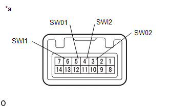
(b) Check the Illuminates.
|
(1) Apply battery voltage to the electric parking brake switch assembly and check that the switch illuminates. OK:
If the result is not as specified, replace the electric parking brake switch assembly. |
|

Installation
INSTALLATION
PROCEDURE
1. INSTALL ELECTRIC PARKING BRAKE SWITCH ASSEMBLY
(a) Engage the 2 guides to install the electric parking brake switch assembly.
(b) Install the 4 screws.
2. INSTALL CONSOLE UPPER PANEL SUB-ASSEMBLY
Click here
.gif)
 Installation
INSTALLATION
CAUTION / NOTICE / HINT
HINT:
Use the same procedure for the RH side and LH side.
The following procedure is for the LH side.
PROCEDURE
1. INSTALL PARKING BRAKE ACT ...

Other materials:
Toyota CH-R Owners Manual > Operating the lights and wipers: Rear window wiper and washer
Operating instructions
Turning the
switch
turns on the rear window wiper and washer as follows:
OFF *1 or
*2
Off
INT *1 or
*2
Intermittent window wiper operation
ON *1 or
*2
Normal window wiper operation
*1: For U.S.A.
*2: For Canada
Washer/wiper dual operation ...
Toyota CH-R Service Manual > Airbag System: Short in Rear Pretensioner Squib RH Circuit (B1920/77-B1923/77)
DESCRIPTION
The rear pretensioner squib RH circuit consists of the airbag sensor assembly
and rear seat 3 point type outer belt assembly RH.
The airbag sensor assembly uses this circuit to deploy the pretensioner when
deployment conditions are met.
These DTCs are stored when a malfunction is ...
Toyota CH-R Owners Manual
- For safety and security
- Instrument cluster
- Operation of each component
- Driving
- Interior features
- Maintenance and care
- When trouble arises
- Vehicle specifications
- For owners
Toyota CH-R Service Manual
- Introduction
- Maintenance
- Audio / Video
- Cellular Communication
- Navigation / Multi Info Display
- Park Assist / Monitoring
- Brake (front)
- Brake (rear)
- Brake Control / Dynamic Control Systems
- Brake System (other)
- Parking Brake
- Axle And Differential
- Drive Shaft / Propeller Shaft
- K114 Cvt
- 3zr-fae Battery / Charging
- Networking
- Power Distribution
- Power Assist Systems
- Steering Column
- Steering Gear / Linkage
- Alignment / Handling Diagnosis
- Front Suspension
- Rear Suspension
- Tire / Wheel
- Tire Pressure Monitoring
- Door / Hatch
- Exterior Panels / Trim
- Horn
- Lighting (ext)
- Mirror (ext)
- Window / Glass
- Wiper / Washer
- Door Lock
- Heating / Air Conditioning
- Interior Panels / Trim
- Lighting (int)
- Meter / Gauge / Display
- Mirror (int)
- Power Outlets (int)
- Pre-collision
- Seat
- Seat Belt
- Supplemental Restraint Systems
- Theft Deterrent / Keyless Entry

0.0108