Toyota CH-R Service Manual: TC and CG Terminal Circuit
DESCRIPTION
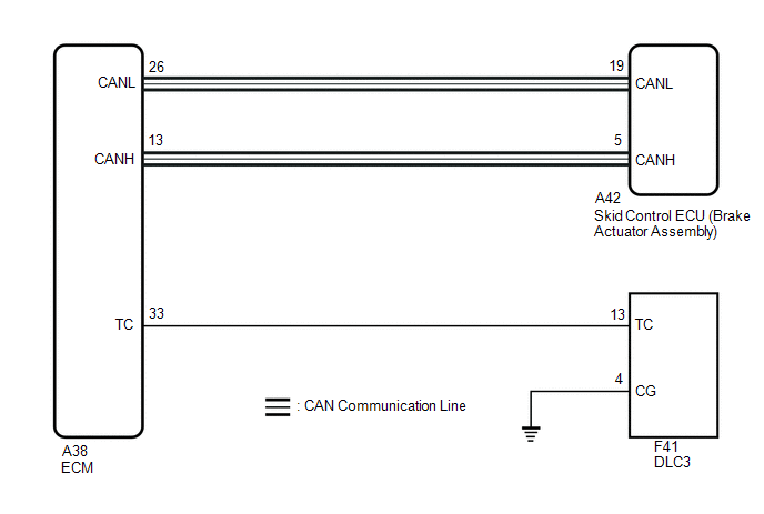
Connecting terminals TC and CG of the DLC3 causes the ECU to display DTCs by blinking the ABS warning and slip indicator lights.
WIRING DIAGRAM
CAUTION / NOTICE / HINT
NOTICE:
When replacing the skid control ECU (brake actuator assembly), perform system variant learning.
Click here
.gif)
HINT:
When the indicator lights continue to blink, a ground short in the wiring of terminal TC of the DLC3 or an internal ground short in one or more ECUs is suspected.
PROCEDURE
|
1. |
CHECK CAN COMMUNICATION SYSTEM |
(a) Check if CAN communication system DTCs are output.
Click here
|
Result |
Proceed to |
|---|---|
|
DTCs are not output. |
A |
|
DTCs are output. |
B |
| B | .gif) |
INSPECT CAN COMMUNICATION SYSTEM
|
|
.gif)
|
2. |
INSPECT DLC3 |
(a) Turn the ignition switch to ON.
|
(b) Measure the voltage according to the value(s) in the table below. Standard Voltage:
|
|
| NG | |
GO TO STEP 4 |
|
|
3. |
REPLACE ECM |
|
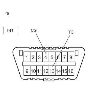
*a |
Front view of DLC3 |
(a) Turn the ignition switch off.
(b) Replace the ECM.
Click here
(c) Using SST, connect terminals TC and CG of the DLC3.
SST: 09843-18040
(d) Check that the ABS warning, slip indicator and brake hold standby indicator lights are blinking.
OK:
The ABS warning, slip indicator and brake hold standby indicator lights are blinking.
HINT:
If troubleshooting has been carried out according to Problem Symptoms Table, refer back to the table and proceed to the next step before replacing parts.
Click here
| OK | |
END |
| NG | |
REPLACE BRAKE ACTUATOR ASSEMBLY |
|
4. |
CHECK HARNESS AND CONNECTOR (TC of DLC3 - ECM) |
(a) Turn the ignition switch off.
(b) Disconnect the A38 ECM connector.
(c) Measure the resistance according to the value(s) in the table below.
Standard Resistance:
|
Tester Connection |
Condition |
Specified Condition |
|---|---|---|
|
F41-13 (TC) - A38-33 (TC) |
Always |
Below 1 Ω |
|
F41-13 (TC) or A38-33 (TC) - Body ground |
Always |
10 kΩ or higher |
| NG | |
REPAIR OR REPLACE HARNESS OR CONNECTOR |
|
|
5. |
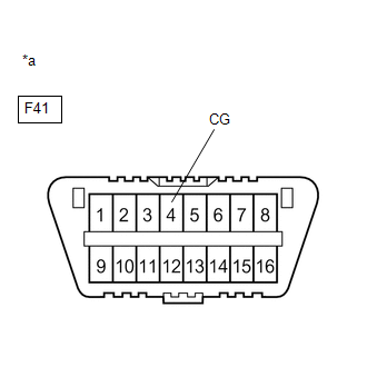
CHECK HARNESS AND CONNECTOR (CG of DLC3 - BODY GROUND) |
|
(a) Measure the resistance according to the value(s) in the table below. Standard Resistance:
|
|
| NG | |
REPAIR OR REPLACE HARNESS OR CONNECTOR |
|
|
6. |
REPLACE ECM |
|
*a |
Front view of DLC3 |
(a) Replace the ECM.
Click here
(b) Using SST, connect terminals TC and CG of the DLC3.
SST: 09843-18040
(c) Check that the ABS warning, slip indicator and brake hold standby indicator lights are blinking.
OK:
The ABS warning, slip indicator and brake hold standby indicator lights are blinking.
HINT:
If troubleshooting has been carried out according to Problem Symptoms Table, refer back to the table and proceed to the next step before replacing parts.
Click here
| OK | |
END |
| NG | |
REPLACE BRAKE ACTUATOR ASSEMBLY |
 Slip Indicator Light does not Come ON
DESCRIPTION
The skid control ECU (brake actuator assembly) is connected to the combination
meter assembly via CAN communication.
CAUTION / NOTICE / HINT
NOTICE:
When replacing the skid control E ...
 Excessive Brake Pedal Travel (No Fluid Leaks and No Air in System)
DESCRIPTION
Depending on the malfunction, the skid control ECU (brake actuator assembly)
prohibits operation of the vehicle stability control system to protect components
and prevent incorrect op ...
Other materials:
Toyota CH-R Service Manual > Rear Airbag Sensor: On-vehicle Inspection
ON-VEHICLE INSPECTION
CAUTION / NOTICE / HINT
CAUTION:
Be sure to correctly follow the removal and installation procedures for the No.
2 side airbag sensors.
PROCEDURE
1. INSPECT NO. 2 SIDE AIRBAG SENSOR (for Vehicle not Involved in Collision)
(a) Perform a diagnostic system check.
Click he ...
Toyota CH-R Service Manual > Power Steering System: Error in Matching of ECUs (C1567)
DESCRIPTION
Based on the steering sensor signal, the power steering ECU assembly determines
if the correct type of steering sensor is installed.
DTC No.
Detection Item
DTC Detection Condition
Trouble Area
Warning Indicate
Return-t ...
Toyota CH-R Owners Manual
- For safety and security
- Instrument cluster
- Operation of each component
- Driving
- Interior features
- Maintenance and care
- When trouble arises
- Vehicle specifications
- For owners
Toyota CH-R Service Manual
- Introduction
- Maintenance
- Audio / Video
- Cellular Communication
- Navigation / Multi Info Display
- Park Assist / Monitoring
- Brake (front)
- Brake (rear)
- Brake Control / Dynamic Control Systems
- Brake System (other)
- Parking Brake
- Axle And Differential
- Drive Shaft / Propeller Shaft
- K114 Cvt
- 3zr-fae Battery / Charging
- Networking
- Power Distribution
- Power Assist Systems
- Steering Column
- Steering Gear / Linkage
- Alignment / Handling Diagnosis
- Front Suspension
- Rear Suspension
- Tire / Wheel
- Tire Pressure Monitoring
- Door / Hatch
- Exterior Panels / Trim
- Horn
- Lighting (ext)
- Mirror (ext)
- Window / Glass
- Wiper / Washer
- Door Lock
- Heating / Air Conditioning
- Interior Panels / Trim
- Lighting (int)
- Meter / Gauge / Display
- Mirror (int)
- Power Outlets (int)
- Pre-collision
- Seat
- Seat Belt
- Supplemental Restraint Systems
- Theft Deterrent / Keyless Entry

0.0119