Toyota CH-R Service Manual: Power Source Circuit
DESCRIPTION
This circuit provides power to operate the blind spot monitor sensor.
WIRING DIAGRAM

CAUTION / NOTICE / HINT
NOTICE:
Inspect the fuses for circuits related to this system before performing the following procedure.
PROCEDURE
|
1. |
CHECK HARNESS AND CONNECTOR (BLIND SPOT MONITOR SENSOR LH (MASTER) POWER SOURCE) |
|
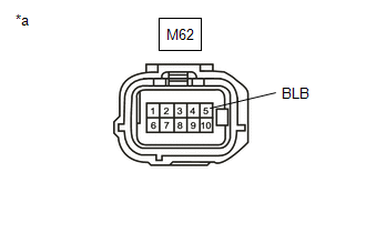
*a |
Front view of wire harness connector (to blind spot monitor sensor LH (Master)) |
(a) Disconnect the blind spot monitor sensor LH (Master) connector.
(b) Measure the voltage according to the value(s) in the table below.
Standard Voltage:
|
Tester Connection |
Switch Condition |
Specified Condition |
|---|---|---|
|
M62-5 (BLB) - Body ground |
Ignition switch to ON |
11 to 14 V |
|
M62-5 (BLB) - Body ground |
Ignition switch off |
Below 1 V |
| NG | .gif) |
REPAIR OR REPLACE HARNESS OR CONNECTOR |
|
.gif)
|
2. |
CHECK HARNESS AND CONNECTOR (BLIND SPOT MONITOR SENSOR LH (MASTER) - BODY GROUND) |
(a) Measure the resistance according to the value(s) in the table below.
Standard Resistance:
|
Tester Connection |
Condition |
Specified Condition |
|---|---|---|
|
M62-10 (BLGD) - Body ground |
Always |
Below 1 Ω |
| NG | |
REPAIR OR REPLACE HARNESS OR CONNECTOR |
|
|
3. |
CHECK HARNESS AND CONNECTOR (BLIND SPOT MONITOR SENSOR RH (SLAVE) POWER SOURCE) |

|
*a |
Front view of wire harness connector (to blind spot monitor sensor RH(Slave)) |
(a) Disconnect the blind spot monitor sensor RH (Slave) connector.
(b) Measure the voltage according to the value(s) in the table below.
Standard Voltage:
|
Tester Connection |
Switch Condition |
Specified Condition |
|---|---|---|
|
M63-5 (BRB) - Body ground |
Ignition switch to ON |
11 to 14 V |
|
M63-5 (BRB) - Body ground |
Ignition switch off |
Below 1 V |
| NG | |
REPAIR OR REPLACE HARNESS OR CONNECTOR |
|
|
4. |
CHECK HARNESS AND CONNECTOR (BLIND SPOT MONITOR SENSOR RH (SLAVE) - BODY GROUND) |
(a) Measure the resistance according to the value(s) in the table below.
Standard Resistance:
|
Tester Connection |
Condition |
Specified Condition |
|---|---|---|
|
M63-10 (BRGD) - Body ground |
Always |
Below 1 Ω |
| OK | |
PROCEED TO NEXT SUSPECTED AREA SHOWN IN PROBLEM SYMPTOMS TABLE |
| NG | |
REPAIR OR REPLACE HARNESS OR CONNECTOR |
 Yaw Rate Sensor (C1A46)
DESCRIPTION
The blind spot monitor sensor receives yaw rate signals from the airbag sensor
assembly via CAN communication.
DTC No.
Detection Item
DTC Detection Con ...

Other materials:
Toyota CH-R Service Manual > Front Brake: Disassembly
DISASSEMBLY
PROCEDURE
1. REMOVE FRONT DISC BRAKE PISTON
(a) Place a piece of cloth between the front disc brake piston and front
disc brake cylinder assembly.
*a
Cloth
...
Toyota CH-R Service Manual > Meter / Gauge System: Meter Illumination does not Dim at Night
DESCRIPTION
In this circuit, the combination meter assembly receives auto dimmer signals
from the main body ECU (multiplex network body ECU) via CAN communication. When
the combination meter assembly receives an auto dimmer signal, it dims the meter
illumination (warning and indicator lights) ...
Toyota CH-R Owners Manual
- For safety and security
- Instrument cluster
- Operation of each component
- Driving
- Interior features
- Maintenance and care
- When trouble arises
- Vehicle specifications
- For owners
Toyota CH-R Service Manual
- Introduction
- Maintenance
- Audio / Video
- Cellular Communication
- Navigation / Multi Info Display
- Park Assist / Monitoring
- Brake (front)
- Brake (rear)
- Brake Control / Dynamic Control Systems
- Brake System (other)
- Parking Brake
- Axle And Differential
- Drive Shaft / Propeller Shaft
- K114 Cvt
- 3zr-fae Battery / Charging
- Networking
- Power Distribution
- Power Assist Systems
- Steering Column
- Steering Gear / Linkage
- Alignment / Handling Diagnosis
- Front Suspension
- Rear Suspension
- Tire / Wheel
- Tire Pressure Monitoring
- Door / Hatch
- Exterior Panels / Trim
- Horn
- Lighting (ext)
- Mirror (ext)
- Window / Glass
- Wiper / Washer
- Door Lock
- Heating / Air Conditioning
- Interior Panels / Trim
- Lighting (int)
- Meter / Gauge / Display
- Mirror (int)
- Power Outlets (int)
- Pre-collision
- Seat
- Seat Belt
- Supplemental Restraint Systems
- Theft Deterrent / Keyless Entry

0.0104