Toyota CH-R Service Manual: Disassembly
DISASSEMBLY
CAUTION / NOTICE / HINT
CAUTION:
Wear protective gloves. Sharp areas on the parts may injure your hands.
PROCEDURE
1. REMOVE SEAT BELT ANCHOR COVER CAP (for RH Side)
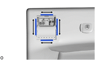
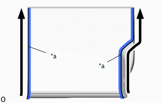
(a) Using a moulding remover A, disengage the claws and guides to separate the rear seat shoulder belt cover with seat belt anchor cover cap as shown in the illustration.

.png) |
Remove in this Direction (1) |
.png) |
Remove in this Direction (2) |
(b) Disengage the guides to remove the seat belt anchor cover cap as shown in the illustration.

.png) |
Remove in this Direction |
2. REMOVE REAR SEAT SHOULDER BELT HOLE COVER (for RH Side)
|
(a) Remove the rear seat shoulder belt hole cover. |
|
3. REMOVE REAR SEATBACK LOCK CONTROL BEZEL (for RH Side)
|
(a) Disengage the claws to remove the rear seatback lock control bezel. |
|
|
(b) Disengage the hooks from the separate type rear seatback cover. |
|
4. REMOVE REAR SEATBACK BOARD SUB-ASSEMBLY RH (for RH Side)
|
(a) Disengage the hook. |
|
|
(b) Open the 2 fasteners as shown in the illustration. |
|
|
(c) Disengage the claws and guides to remove the rear seatback board sub-assembly RH. |
|
5. REMOVE REAR SEAT HEADREST SUPPORT (for RH Side)
(a) w/o Occupant Classification System:
(1) Disengage the claws to remove the 2 rear seat headrest supports as shown in the illustration.

.png) |
Remove in this Direction |
(b) w/ Occupant Classification System:
(1) Disengage the claws to remove the 2 rear seat headrest supports as shown in the illustration.

.png) |
Remove in this Direction |
6. REMOVE REAR SEAT CENTER HEADREST SUPPORT (for RH Side)
(a) Disengage the claws to remove the 2 rear seat center headrest supports as shown in the illustration.

.png) |
Remove in this Direction |
7. REMOVE SEPARATE TYPE REAR SEATBACK COVER WITH PAD (for RH Side)
|
(a) Pass the rear center seat outer belt assembly through the separate type rear seatback cover with pad and remove the separate type rear seatback cover with pad from the rear seatback frame sub-assembly RH. |
|
8. REMOVE SEPARATE TYPE REAR SEATBACK COVER (for RH Side)
(a) Using a screwdriver, disengage the claws to remove the separate type rear seatback cover from the separate type rear seatback pad RH as shown in the illustration.

|
*a |
Screwdriver |
- |
- |
9. REMOVE REAR CENTER SEAT OUTER BELT ASSEMBLY (for RH Side)
Click here .gif)
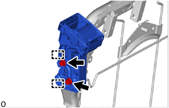
10. REMOVE REAR SEATBACK LOCK ASSEMBLY RH (for RH Side)
|
(a) Remove the 2 bolts. |
|
(b) Disengage the guides to rear seatback lock assembly RH.
11. REMOVE REAR SEATBACK LOCK CONTROL BEZEL (for LH Side)
|
(a) Disengage the claws to remove the rear seatback lock control bezel. |
|
|
(b) Disengage the hooks from the separate type rear seatback cover. |
|
12. REMOVE REAR SEATBACK BOARD SUB-ASSEMBLY LH (for LH Side)
|
(a) Disengage the hook. |
|
|
(b) Open the 2 fasteners as shown in the illustration. |
|
|
(c) Disengage the claws and guides to remove the rear seatback board sub-assembly LH. |
|
13. REMOVE REAR SEAT HEADREST SUPPORT (for LH Side)
(a) w/o Occupant Classification System:
(1) Disengage the claws to remove the 2 rear seat headrest supports as shown in the illustration.

.png) |
Remove in this Direction |
(b) w/ Occupant Classification System:

.png) |
Remove in this Direction |
(1) Disengage the claws to remove the 2 rear seat headrest supports as shown in the illustration.
14. REMOVE SEPARATE TYPE REAR SEATBACK COVER WITH PAD (for LH Side)
|
(a) Remove the separate type rear seatback cover with pad from the rear seatback frame sub-assembly LH. |
|
15. REMOVE SEPARATE TYPE REAR SEATBACK COVER (for LH Side)
(a) Using a screwdriver, disengage the claws to remove the separate type rear seatback cover from the separate type rear seatback pad LH as shown in the illustration.

|
*a |
Screwdriver |
- |
- |
16. REMOVE REAR SEATBACK LOCK ASSEMBLY LH (for LH Side)
|
(a) Remove the 2 bolts. |
|
(b) Disengage the guides to rear seatback lock assembly LH.
17. REMOVE REAR DOOR SCUFF PANEL LH (w/ Occupant Classification System)
|
(a) Disengage the claws to remove the rear door scuff panel LH. |
|
18. REMOVE REAR DOOR SCUFF PANEL RH (w/ Occupant Classification System)
HINT:
Use the same procedure for the RH side and LH side.
19. REMOVE REAR NO. 2 SEAT COVER BEZEL (w/ Occupant Classification System)
|
(a) Remove the 3 screws and rear No. 2 seat cover bezel. |
|
20. REMOVE REAR NO. 1 SEAT COVER BEZEL (w/ Occupant Classification System)
HINT:
Use the same procedure for the No. 1 seat cover bezel and No. 2 seat cover bezel.
21. REMOVE BENCH TYPE REAR SEAT CUSHION COVER
(a) w/o Occupant Classification System:
(1) Disengage the hook and loop fastener and hooks.

|
*a |
Hook and Loop Fastener |
- |
- |
(b) w/ Occupant Classification System:
(1) Disengage the hook and loop fastener and hooks.

|
*a |
Hook and Loop Fastener |
- |
- |
(c) Remove the rear seat cushion pad from the No. 1 rear seat cushion pad sub-assembly.

(d) Using a screwdriver, disengage the claws to remove the bench type rear seat cushion cover from the No. 1 rear seat cushion pad sub-assembly as shown in the illustration.

|
*a |
Screwdriver |
- |
- |
 Removal
REMOVAL
CAUTION / NOTICE / HINT
CAUTION:
Wear protective gloves. Sharp areas on the parts may injure your hands.
PROCEDURE
1. REMOVE REAR SEAT HEADREST ASSEMBLY (for RH Side)
(a) Remove the rear ...
 Installation
INSTALLATION
CAUTION / NOTICE / HINT
CAUTION:
Wear protective gloves. Sharp areas on the parts may injure your hands.
PROCEDURE
1. INSTALL REAR SEAT CUSHION LOCK HOOK
(a) Engage the claws to ins ...
Other materials:
Toyota CH-R Service Manual > Manual Headlight Beam Level Control System: Precaution
PRECAUTION
EXPRESSIONS OF IGNITION SWITCH
The type of ignition switch used on this model differs depending on the specifications
of the vehicle. The expressions listed in the table below are used in this section.
Expression
Ignition Switch (Position)
Engine Swit ...
Toyota CH-R Owners Manual > BSM (Blind Spot Monitor): BSM function
The BSM function uses radar sensors to detect the following vehicles traveling
in adjacent lanes and advises the driver of the presence of such vehicles via the
indicators on the outside rear view mirrors.
Vehicles that are traveling in areas that are not visible using the outside
rea ...
Toyota C-HR (AX20) 2023-2025 Owner's Manual
Toyota CH-R Owners Manual
- For safety and security
- Instrument cluster
- Operation of each component
- Driving
- Interior features
- Maintenance and care
- When trouble arises
- Vehicle specifications
- For owners
Toyota CH-R Service Manual
- Introduction
- Maintenance
- Audio / Video
- Cellular Communication
- Navigation / Multi Info Display
- Park Assist / Monitoring
- Brake (front)
- Brake (rear)
- Brake Control / Dynamic Control Systems
- Brake System (other)
- Parking Brake
- Axle And Differential
- Drive Shaft / Propeller Shaft
- K114 Cvt
- 3zr-fae Battery / Charging
- Networking
- Power Distribution
- Power Assist Systems
- Steering Column
- Steering Gear / Linkage
- Alignment / Handling Diagnosis
- Front Suspension
- Rear Suspension
- Tire / Wheel
- Tire Pressure Monitoring
- Door / Hatch
- Exterior Panels / Trim
- Horn
- Lighting (ext)
- Mirror (ext)
- Window / Glass
- Wiper / Washer
- Door Lock
- Heating / Air Conditioning
- Interior Panels / Trim
- Lighting (int)
- Meter / Gauge / Display
- Mirror (int)
- Power Outlets (int)
- Pre-collision
- Seat
- Seat Belt
- Supplemental Restraint Systems
- Theft Deterrent / Keyless Entry
0.0109


