Toyota CH-R Service Manual: Reassembly
REASSEMBLY
PROCEDURE
1. INSTALL NO. 1 COOLER THERMISTOR
Click here
.gif)
2. INSTALL NO. 2 RADIATOR CASE SUB-ASSEMBLY
|
(a) Install the No. 2 radiator case sub-assembly with the 6 screws. |
|
.png)
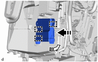
3. INSTALL NO. 1 COOLER EVAPORATOR SUB-ASSEMBLY

.png) |
Install in this Direction |
(a) Install the No. 1 cooler evaporator sub-assembly with No. 1 cooler thermistor as shown in the illustration.
(b) Connect the connector.
4. INSTALL RADIATOR CASE SUB-ASSEMBLY
(a) Engage the claws and to install the radiator case sub-assembly.
.png)
(b) Install the 3 screws.
5. INSTALL HEAT EXCHANGER CASE
|
(a) Engage the 2 claws and guide, and install the heat exchanger case with the screw. |
|
.png)
|
(b) Install the bracket with the 2 screws. |
|
.png)
6. INSTALL COOLER EXPANSION VALVE
|
(a) Install the grommet. |
|
.png)
(b) Sufficiently apply compressor oil to 2 new O-rings and fitting surfaces of the No. 1 cooler evaporator sub-assembly.
Compressor Oil:
VC100YF or equivalent
(c) Install the 2 O-rings to the No. 1 cooler evaporator sub-assembly.
NOTICE:
Keep the O-rings and O-ring fitting surfaces free of foreign matter.
|
(d) Using a 4 mm hexagon socket wrench, install the cooler expansion valve with the 2 hexagon bolts. Torque: 4.5 N·m {46 kgf·cm, 40 in·lbf} |
|
.png)
7. INSTALL HEATER RADIATOR UNIT SUB-ASSEMBLY

|
|
Install in this Direction |
(a) Install the heater radiator unit sub-assembly as shown in the illustration.
|
(b) Install the 3 screws. |
|
.png)
8. INSTALL HEATER CLAMP
|
(a) Engage the claws to install the heater clamp. |
|
.png)
(b) Install the screw.
9. INSTALL HEATER PIPE GROMMET
|
(a) Install the heater pipe grommet. |
|
.png)
10. INSTALL NO. 2 AIR CONDITIONING RADIATOR DAMPER SERVO SUB-ASSEMBLY
(a) Install the No. 2 air conditioning radiator damper servo sub-assembly as shown in the illustration.

|
|
Install in this Direction |
(b) Turn the No. 2 air conditioning radiator damper servo sub-assembly to engage the claw as shown in the illustration.
.png)
|
|
Install in this Direction |
11. INSTALL NO. 1 AIR CONDITIONING RADIATOR DAMPER SERVO SUB-ASSEMBLY
(a) for Lower RH Side:
(1) Install the No. 1 air conditioning radiator damper servo sub-assembly as shown in the illustration.

|
|
Install in this Direction |
(2) Turn the No. 1 air conditioning radiator damper servo sub-assembly to engage the claw as shown in the illustration.

|
|
Install in this Direction |
(3) Engage the snap.
(b) for Upper RH Side:
(1) Install the No. 1 air conditioning radiator damper servo sub-assembly as shown in the illustration.

|
|
Install in this Direction |
(2) Turn the No. 1 air conditioning radiator damper servo sub-assembly to engage the claw as shown in the illustration.

|
|
Install in this Direction |
(c) for Lower LH Side:
(1) Install the No. 1 air conditioning radiator damper servo sub-assembly as shown in the illustration.

|
|
Install in this Direction |
(2) Turn the No. 1 air conditioning radiator damper servo sub-assembly to engage the claw as shown in the illustration.

|
|
Install in this Direction |
(3) Engage the snap.
(d) for Upper LH Side:
(1) Install the No. 1 air conditioning radiator damper servo sub-assembly as shown in the illustration.

|
|
Install in this Direction |
(2) Turn the No. 1 air conditioning radiator damper servo sub-assembly to engage the claw as shown in the illustration.

|
|
Install in this Direction |
12. INSTALL NO. 2 COOLER UNIT DRAIN HOSE
|
(a) Install the No. 2 cooler unit drain hose. |
|
.png)
13. INSTALL DRAIN COOLER HOSE
|
(a) Install the drain cooler hose. |
|
.png)
14. INSTALL AIR CONDITIONING HARNESS ASSEMBLY
(a) Engage clamps to install the air conditioning harness assembly.
.png)
(b) Connect the 5 connectors.
15. INSTALL AIR CONDITIONING AMPLIFIER ASSEMBLY
(a) Engage the guides to temporarily install the air conditioning amplifier assembly as shown in the illustration.
|
|
Install in this Direction (1) |
.png) |
Install in this Direction (2) |
|
(b) Install the air conditioning amplifier assembly with the screw. |
|
.png)
(c) Connect the connector.
16. INSTALL HEATER COVER (w/o PTC Heater)
(a) Install the heater cover with the 2 screws as shown in the illustration.

|
|
Install in this Direction |
17. INSTALL QUICK HEATER ASSEMBLY (w/ PTC Heater)

|
|
Install in this Direction |
(a) Install the quick heater assembly with the 2 screws as shown in the illustration.
18. INSTALL NO. 2 HEATER COVER (w/ PTC Heater)
|
(a) Install the No. 2 heater cover with the screw. |
|
.png)
19. INSTALL BLOWER ASSEMBLY
Click here
20. INSTALL NO. 3 COOLER UNIT DRAIN HOSE
|
(a) Install the No. 3 cooler unit drain hose. |
|
.png)
21. INSTALL NO. 3 INSTRUMENT PANEL WIRE (w/ PTC Heater)
|
(a) Engage the clamps to install the No. 3 instrument panel wire. |
|
.png)
(b) Connect the connector.
22. INSTALL COVER (except Cold Area Specification Vehicles)
|
(a) Engage the claws to install the cover. |
|
.png)
23. INSTALL AIR CONDITIONING DUCT SUB-ASSEMBLY
|
(a) Engage the guide to install the air conditioning duct sub-assembly. |
|
.png)
24. INSTALL NO. 2 AIR DUCT
(a) Engage the claws to install the No. 2 air duct as shown in the illustration.

|
|
Install in this Direction |
(b) Install the screw.
25. INSTALL ID CODE BOX (IMMOBILISER CODE ECU)
Click here
 Disassembly
DISASSEMBLY
PROCEDURE
1. PRECAUTION
NOTICE:
Make sure to perform initialization after replacing the air conditioning radiator
damper servo sub-assembly. If initialization is not performed, the a ...
 Installation
INSTALLATION
PROCEDURE
1. INSTALL LOWER DEFROSTER NOZZLE ASSEMBLY
(a) Engage the claws to install the lower defroster nozzle assembly.
2. ...
Other materials:
Toyota CH-R Service Manual > Back Door: Adjustment
ADJUSTMENT
CAUTION / NOTICE / HINT
*a
Centering Bolt
*b
Standard Bolt
HINT:
Centering bolts are used to install the door hinges to the door. The
door cannot be adjusted with the centering bolts installed. Substitute the
...
Toyota CH-R Service Manual > Heating / Air Conditioning: Room Temperature Sensor
Components
COMPONENTS
ILLUSTRATION
*1
COOLER THERMISTOR (ROOM TEMPERATURE SENSOR)
*2
INSTRUMENT CLUSTER FINISH PANEL GARNISH ASSEMBLY
*3
INSTRUMENT PANEL LOWER CENTER FINISH PANEL
-
-
Inspe ...
Toyota C-HR (AX20) 2023-2025 Owner's Manual
Toyota CH-R Owners Manual
- For safety and security
- Instrument cluster
- Operation of each component
- Driving
- Interior features
- Maintenance and care
- When trouble arises
- Vehicle specifications
- For owners
Toyota CH-R Service Manual
- Introduction
- Maintenance
- Audio / Video
- Cellular Communication
- Navigation / Multi Info Display
- Park Assist / Monitoring
- Brake (front)
- Brake (rear)
- Brake Control / Dynamic Control Systems
- Brake System (other)
- Parking Brake
- Axle And Differential
- Drive Shaft / Propeller Shaft
- K114 Cvt
- 3zr-fae Battery / Charging
- Networking
- Power Distribution
- Power Assist Systems
- Steering Column
- Steering Gear / Linkage
- Alignment / Handling Diagnosis
- Front Suspension
- Rear Suspension
- Tire / Wheel
- Tire Pressure Monitoring
- Door / Hatch
- Exterior Panels / Trim
- Horn
- Lighting (ext)
- Mirror (ext)
- Window / Glass
- Wiper / Washer
- Door Lock
- Heating / Air Conditioning
- Interior Panels / Trim
- Lighting (int)
- Meter / Gauge / Display
- Mirror (int)
- Power Outlets (int)
- Pre-collision
- Seat
- Seat Belt
- Supplemental Restraint Systems
- Theft Deterrent / Keyless Entry

0.0129