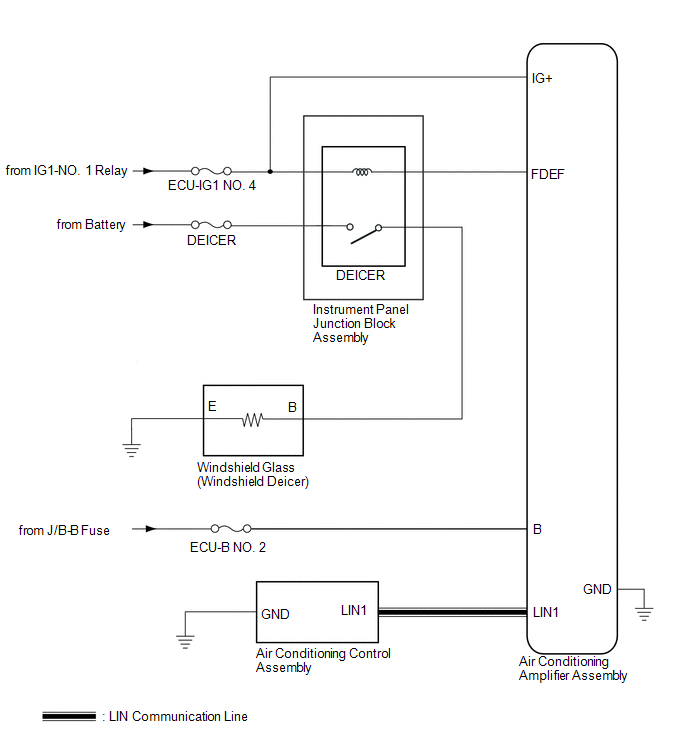
Toyota CH-R Service Manual: System Diagram
SYSTEM DIAGRAM

 Parts Location
PARTS LOCATION
ILLUSTRATION
*A
for TMMT Made
*B
for TMC Made
*1
NO. 1 ENGINE ROOM RELAY BLOCK
- DEICER FUSE
*2 ...
 System Description
SYSTEM DESCRIPTION
GENERAL
The windshield deicer thin heater wires are attached to the inside of the windshield
glass to help deice the window surface more quickly. The indicator light illuminates ...
Other materials:
Toyota CH-R Service Manual > Toyota Entune System: Dtc Check / Clear
DTC CHECK / CLEAR
CHECK DTC
(a) Connect the Techstream to the DLC3.
(b) Turn the ignition switch to ON.
(c) Turn the Techstream on.
(d) Enter the following menus: Body Electrical / Telematics / Trouble Codes.
Body Electrical > Telematics > Trouble Codes
(e) Check for DTCs.
Click here
...
Toyota CH-R Owners Manual > For safe use: Front passenger occupant classification system
Your vehicle is equipped with a front passenger occupant classification
system. This system detects the conditions of the front passenger seat and activates
or deactivates the devices for the front passenger.
SRS warning light
Seat belt reminder light
"AIR BAG O ...
Toyota CH-R Owners Manual
- For safety and security
- Instrument cluster
- Operation of each component
- Driving
- Interior features
- Maintenance and care
- When trouble arises
- Vehicle specifications
- For owners
Toyota CH-R Service Manual
- Introduction
- Maintenance
- Audio / Video
- Cellular Communication
- Navigation / Multi Info Display
- Park Assist / Monitoring
- Brake (front)
- Brake (rear)
- Brake Control / Dynamic Control Systems
- Brake System (other)
- Parking Brake
- Axle And Differential
- Drive Shaft / Propeller Shaft
- K114 Cvt
- 3zr-fae Battery / Charging
- Networking
- Power Distribution
- Power Assist Systems
- Steering Column
- Steering Gear / Linkage
- Alignment / Handling Diagnosis
- Front Suspension
- Rear Suspension
- Tire / Wheel
- Tire Pressure Monitoring
- Door / Hatch
- Exterior Panels / Trim
- Horn
- Lighting (ext)
- Mirror (ext)
- Window / Glass
- Wiper / Washer
- Door Lock
- Heating / Air Conditioning
- Interior Panels / Trim
- Lighting (int)
- Meter / Gauge / Display
- Mirror (int)
- Power Outlets (int)
- Pre-collision
- Seat
- Seat Belt
- Supplemental Restraint Systems
- Theft Deterrent / Keyless Entry
0.0132
