Toyota CH-R Service Manual: Inspection
INSPECTION
PROCEDURE
1. INSPECT REAR HEIGHT CONTROL SENSOR SUB-ASSEMBLY LH
(a) Preparation for check
(1) Confirm the standard, high and low positions of the link that will be used in the following inspection.
- The standard position is 58° from the maximum link angle (high) and 51° from the maximum link angle (low).
- The high position (+33.85°) is 24.15° from the maximum link angle (high).
- The low position (-33.85°) is 17.15° from the maximum link angle (low).
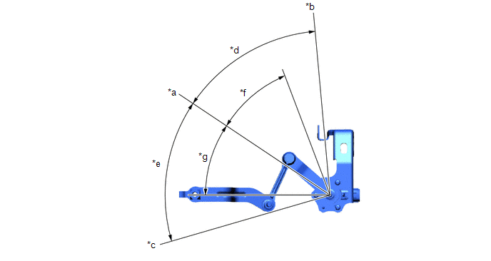
|
*a |
Standard Position |
*b |
Maximum Link Angle (Low) |
|
*c |
Maximum Link Angle (High) |
*d |
51° |
|
*e |
58° |
*f |
-33.85° |
|
*g |
+33.85° |
- |
- |
(2) Connect 3 dry cell batteries (1.5 V) in series.
NOTICE:
Do not use rechargeable batteries as they may not output a voltage of 1.5 V.
(3) Connect a positive (+) lead from the batteries to terminal 3 (SHB) and a negative (-) lead to terminal 1 (SHG).
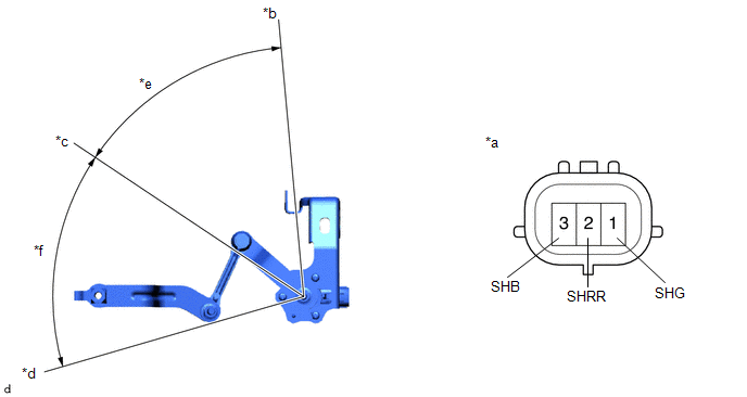
|
*a |
Component without harness connected (Rear Height Control Sensor Sub-assembly LH) |
*b |
Low |
|
*c |
Standard Position |
*d |
High |
|
*e |
-33.85° |
*f |
+33.85° |
(4) Measure the voltage between terminals 2 (SHRR) and 1 (SHG) while slowly moving the link up and down.
Standard Voltage:
|
Tester Connection |
Condition |
Specified Condition |
|---|---|---|
|
1 (SHG) - 2 (SHRR) |
+33.85° (High) |
4.15 V |
|
1 (SHG) - 2 (SHRR) |
0° (Standard position) |
2.5 V |
|
1 (SHG) - 2 (SHRR) |
-33.85° (Low) |
1.04 V |
If the result is not as specified, replace the rear height control sensor sub-assembly LH.
 Removal
REMOVAL
CAUTION / NOTICE / HINT
The necessary procedures (adjustment, calibration, initialization or registration)
that must be performed after parts are removed and installed, or replaced during ...
 Installation
INSTALLATION
PROCEDURE
1. INSTALL REAR HEIGHT CONTROL SENSOR SUB-ASSEMBLY LH
(a) Engage the hook.
*a
...
Other materials:
Toyota CH-R Service Manual > Park / Neutral Position Switch: On-vehicle Inspection
ON-VEHICLE INSPECTION
PROCEDURE
1. INSPECT PARK/NEUTRAL POSITION SWITCH OPERATION
(a) Apply the parking brake.
(b) Turn the ignition switch to ON.
(c) Depress the brake pedal and check that the engine starts when the shift lever
is in N or P, but does not start in any other position.
(d) Che ...
Toyota CH-R Service Manual > Continuously Variable Transaxle System: Mechanical System Tests
MECHANICAL SYSTEM TESTS
SHIFT TIME LAG TEST
NOTICE:
This test must be conducted after checking and confirming that the engine
is operating normally.
Perform this test while the CVT fluid temperature is between 50 and
100°C (122 and 212°F).
Perform this test with the A/C ...
Toyota C-HR (AX20) 2023-2025 Owner's Manual
Toyota CH-R Owners Manual
- For safety and security
- Instrument cluster
- Operation of each component
- Driving
- Interior features
- Maintenance and care
- When trouble arises
- Vehicle specifications
- For owners
Toyota CH-R Service Manual
- Introduction
- Maintenance
- Audio / Video
- Cellular Communication
- Navigation / Multi Info Display
- Park Assist / Monitoring
- Brake (front)
- Brake (rear)
- Brake Control / Dynamic Control Systems
- Brake System (other)
- Parking Brake
- Axle And Differential
- Drive Shaft / Propeller Shaft
- K114 Cvt
- 3zr-fae Battery / Charging
- Networking
- Power Distribution
- Power Assist Systems
- Steering Column
- Steering Gear / Linkage
- Alignment / Handling Diagnosis
- Front Suspension
- Rear Suspension
- Tire / Wheel
- Tire Pressure Monitoring
- Door / Hatch
- Exterior Panels / Trim
- Horn
- Lighting (ext)
- Mirror (ext)
- Window / Glass
- Wiper / Washer
- Door Lock
- Heating / Air Conditioning
- Interior Panels / Trim
- Lighting (int)
- Meter / Gauge / Display
- Mirror (int)
- Power Outlets (int)
- Pre-collision
- Seat
- Seat Belt
- Supplemental Restraint Systems
- Theft Deterrent / Keyless Entry
0.0114