Toyota CH-R Service Manual: Headlight Ecu
Components
COMPONENTS
ILLUSTRATION

|
*1 |
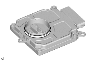
HEADLIGHT ECU SUB-ASSEMBLY |
*2 |
HEADLIGHT GASKET |
|
● |
Non-reusable part |
- |
- |
Installation
INSTALLATION
CAUTION / NOTICE / HINT
HINT:
- Use the same procedure for the RH side and LH side.
- The following procedure is for the LH side.
PROCEDURE
1. INSTALL HEADLIGHT GASKET
(a) Install a new headlight gasket.
2. INSTALL HEADLIGHT ECU SUB-ASSEMBLY
(a) Connect the connector.
(b) Install the connector cover to the headlight ECU sub-assembly.
(c) Install the headlight ECU sub-assembly with the 3 screws.
NOTICE:
If the headlight ECU sub-assembly has been struck or dropped, replace it with a new one.
3. INSTALL HEADLIGHT ASSEMBLY
Click here
.gif)
Removal
REMOVAL
CAUTION / NOTICE / HINT
The necessary procedures (adjustment, calibration, initialization or registration) that must be performed after parts are removed and installed, or replaced the during headlight ECU sub-assembly removal/ installation are shown below.
Necessary Procedure After Parts Removed/Installed/Replaced|
Replacement Part or Procedure |
Necessary Procedures |
Effects/Inoperative when not performed |
Link |
|---|---|---|---|
|
Disconnect cable from negative battery terminal |
Initialize back door lock |
Power door lock control system |
|
|
Memorize steering angle neutral point |
Lane departure alert system (w/ Steering Control) |
|
|
|
Pre-collision system |
|||
|
Headlight ECU sub-assembly LH |
|
Automatic headlight beam level control system |
|
NOTICE:
If the headlight ECU sub-assembly RH is replaced with a new one, vehicle information registration and initialization are not necessary.
HINT:
- Use the same procedure for the RH side and LH side.
- The following procedure is for the LH side.
PROCEDURE
1. REMOVE HEADLIGHT ASSEMBLY
Click here
.gif)
2. REMOVE HEADLIGHT ECU SUB-ASSEMBLY
NOTICE:
Make sure to replace the headlight gasket with a new one. Failure to do so may cause water ingress.
|
(a) Remove the 3 screws. |
|

|
(b) Separate the connector cover from the headlight ECU sub-assembly. |
|

|
(c) Disconnect the connector to remove the headlight ECU sub-assembly. NOTICE: If the headlight ECU sub-assembly has been struck or dropped, replace it with a new one. |
|

3. REMOVE HEADLIGHT GASKET
NOTICE:
Make sure to replace the headlight gasket with a new one. Failure to do so may cause water ingress.
|
(a) Remove the headlight gasket. |
|
 Installation
INSTALLATION
PROCEDURE
1. INSTALL HEADLIGHT DIMMER SWITCH ASSEMBLY
(a) Engage the claws to install the headlight dimmer switch assembly as shown
in the illustration.
Instal ...
 Headlight Leveling Switch
Components
COMPONENTS
ILLUSTRATION
*1
HEADLIGHT LEVELING SWITCH
*2
INSTRUMENT CLUSTER FINISH PANEL SUB-ASSEMBLY
Removal
REMOVAL
PROCEDU ...
Other materials:
Toyota CH-R Service Manual > Can Communication System: Check Bus 5 Lines for Short Circuit
DESCRIPTION
There may be a short circuit between the CAN main bus lines and/or CAN branch
lines when the resistance between terminals 15 (CA5H) and 16 (CA5L) of the central
gateway ECU (network gateway ECU) is below 54 Ω.
Symptom
Trouble Area
Resistance ...
Toyota CH-R Service Manual > Front Lower Ball Joint: Installation
INSTALLATION
CAUTION / NOTICE / HINT
HINT:
Use the same procedure for the RH side and LH side.
The following procedure is for the LH side.
PROCEDURE
1. INSTALL FRONT LOWER BALL JOINT ASSEMBLY
(a) Secure the front axle assembly in a vise using aluminum plates.
NOTICE:
Do not ...
Toyota CH-R Owners Manual
- For safety and security
- Instrument cluster
- Operation of each component
- Driving
- Interior features
- Maintenance and care
- When trouble arises
- Vehicle specifications
- For owners
Toyota CH-R Service Manual
- Introduction
- Maintenance
- Audio / Video
- Cellular Communication
- Navigation / Multi Info Display
- Park Assist / Monitoring
- Brake (front)
- Brake (rear)
- Brake Control / Dynamic Control Systems
- Brake System (other)
- Parking Brake
- Axle And Differential
- Drive Shaft / Propeller Shaft
- K114 Cvt
- 3zr-fae Battery / Charging
- Networking
- Power Distribution
- Power Assist Systems
- Steering Column
- Steering Gear / Linkage
- Alignment / Handling Diagnosis
- Front Suspension
- Rear Suspension
- Tire / Wheel
- Tire Pressure Monitoring
- Door / Hatch
- Exterior Panels / Trim
- Horn
- Lighting (ext)
- Mirror (ext)
- Window / Glass
- Wiper / Washer
- Door Lock
- Heating / Air Conditioning
- Interior Panels / Trim
- Lighting (int)
- Meter / Gauge / Display
- Mirror (int)
- Power Outlets (int)
- Pre-collision
- Seat
- Seat Belt
- Supplemental Restraint Systems
- Theft Deterrent / Keyless Entry

0.0102