Toyota CH-R Service Manual: Installation
INSTALLATION
CAUTION / NOTICE / HINT
HINT:
- Use the same procedure for the RH side and LH side.
- The following procedure is for the LH side.
PROCEDURE
1. INSTALL FRONT DOOR FRONT WINDOW FRAME MOULDING
(a) Using an air riveter or hand riveter with a nose piece, install the front door front window frame moulding with 2 new rivets.

NOTICE:
To prevent damage, when installing the front door front window frame moulding, make sure that there are enough people available to hold it securely.
HINT:
If the mandrel of the rivet does not come off on the first operation of the rivet gun, slide the rivet gun forward on the mandrel and operate it again.
NOTICE:
- Do not pry the rivet with the riveter, as this will cause damage to
the riveter and mandrel.

*a
Riveter
*b
Mandrel
*c
Incorrect
- Confirm that the rivets are seated properly against the moulding.

*a
Riveter
*b
Incorrect
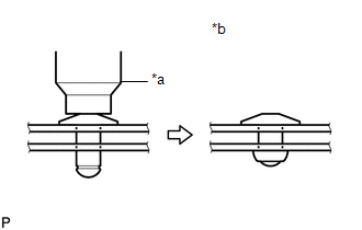
- Do not tilt the riveter when installing the rivet to the moulding.
- Do not leave any space between the rivet head and moulding.
- Do not leave any space between the moulding and door frame. Firmly hold
the 2 items together while installing the rivet.
*a
Riveter
*b
Incorrect
|
(b) Install the front door panel sub-assembly with the 4 bolts <A>. Torque: for TMMT Made : 26 N·m {265 kgf·cm, 19 ft·lbf} for TMC Made : 21 N·m {214 kgf·cm, 15 ft·lbf} NOTICE: To prevent damage, when installing the front door panel sub-assembly, make sure that there are enough people available to hold it securely. |
|

(c) Install the bolt <B>.
Torque:
30 N·m {306 kgf·cm, 22 ft·lbf}
|
(d) Using a brush, apply anti-rust coating to each front door hinge assembly as shown in the illustration. |
|

(e) Connect each connector.
(f) Engage each clamp.
2. INSTALL COWL SIDE TRIM BOARD
Click here
.gif)
3. INSTALL FRONT DOOR SCUFF PLATE
Click here
4. INSTALL FRONT DOOR UPPER WINDOW FRAME MOULDING
(a) Engage the guide to temporarily install the front door upper window frame moulding to the door frame.

(b) Using an air riveter or hand riveter with a nose piece, install the front door upper window frame moulding with 6 new rivets.
HINT:
If the mandrel of the rivet does not come off on the first operation of the rivet gun, slide the rivet gun forward on the mandrel and operate it again.
NOTICE:
- Do not pry the rivet with the riveter, as this will cause damage to
the riveter and mandrel.
*a
Riveter
*b
Mandrel
*c
Incorrect
- Confirm that the rivets are seated properly against the moulding.
*a
Riveter
*b
Incorrect
- Do not tilt the riveter when installing the rivet to the moulding.
- Do not leave any space between the rivet head and moulding.
- Do not leave any space between the moulding and door frame. Firmly hold
the 2 items together while installing the rivet.
*a
Riveter
*b
Incorrect
5. INSTALL FRONT DOOR FIX WINDOW GLASS
Click here
6. INSTALL FRONT DOOR FRONT LOWER FRAME SUB-ASSEMBLY
Click here
7. INSTALL FRONT DOOR GLASS RUN
Click here
8. INSTALL DOOR FRAME UPPER GARNISH
Click here
9. CONNECT FRONT DOOR WEATHERSTRIP
(a) Engage the clips to connect the front door weatherstrip.
10. INSTALL FRONT DOOR OUTSIDE MOULDING SUB-ASSEMBLY
HINT:
When installing a new front door outside moulding sub-assembly, heat the vehicle body and front door outside moulding sub-assembly using a heat light.
Heating Temperature|
Item |
Temperature |
|---|---|
|
Vehicle Body |
40 to 60°C (104 to 140°F) |
|
Front Door Outside Moulding Sub-assembly |
20 to 30°C (68 to 86°F) |
CAUTION:
- Do not touch the heat light and heated parts, touching the heat light may result in burns.
- Touching heated parts for a long time may result in burns.
.png)
|
*a |
Heated Part |
|
*b |
Heat Light |
NOTICE:
Do not heat the vehicle body or front door outside moulding sub-assembly excessively.
(a) Clean the vehicle body surface.
(1) Using a heat light, heat the vehicle body surface.
(2) Remove any double-sided tape from the vehicle body.
(3) Wipe off any tape adhesive residue with cleaner.
(b) Install a new front door outside moulding sub-assembly.

|
*a |
Double-sided Tape |
.png) |
Install in this Direction (1) |
.png) |
Install in this Direction (2) |
(1) Using a heat light, heat the vehicle body and front door outside moulding sub-assembly.
(2) Remove the release paper from the front door outside moulding sub-assembly.
HINT:
After removing the release paper, keep the exposed adhesive free from foreign matter.
(3) Engage the guide and clip and attach the double-sided tape and caulking sponge to install the front door outside moulding sub-assembly.
HINT:
Press the front door outside moulding sub-assembly firmly to install it.
(c) Remove the protective tape.
11. INSTALL FRONT DOOR BELT MOULDING ASSEMBLY
Click here
 Components
COMPONENTS
ILLUSTRATION
*A
for TMMT Made
*B
for TMC Made
*1
DOOR FRAME UPPER GARNISH
*2
FRONT DOOR FIX ...
 Removal
REMOVAL
CAUTION / NOTICE / HINT
The necessary procedures (adjustment, calibration, initialization or registration)
that must be performed after parts are removed and installed, or replaced during ...
Other materials:
Toyota CH-R Service Manual > Rear Brake(for Tmmt Made): Disassembly
DISASSEMBLY
CAUTION / NOTICE / HINT
NOTICE:
If the rear disc brake cylinder assembly has been disassembled, perform
air bleeding for the rear disc brake cylinder.
Click here
Make sure not to scratch, damage or apply excessive force to any of
the internal componen ...
Toyota CH-R Service Manual > Vehicle Stability Control System: Excessive Brake Pedal Travel (No Fluid Leaks and No Air in System)
DESCRIPTION
Depending on the malfunction, the skid control ECU (brake actuator assembly)
prohibits operation of the vehicle stability control system to protect components
and prevent incorrect operation when DTCs are stored.
If the switching solenoid is disabled due to prohibition of the vehic ...
Toyota C-HR (AX20) 2023-2025 Owner's Manual
Toyota CH-R Owners Manual
- For safety and security
- Instrument cluster
- Operation of each component
- Driving
- Interior features
- Maintenance and care
- When trouble arises
- Vehicle specifications
- For owners
Toyota CH-R Service Manual
- Introduction
- Maintenance
- Audio / Video
- Cellular Communication
- Navigation / Multi Info Display
- Park Assist / Monitoring
- Brake (front)
- Brake (rear)
- Brake Control / Dynamic Control Systems
- Brake System (other)
- Parking Brake
- Axle And Differential
- Drive Shaft / Propeller Shaft
- K114 Cvt
- 3zr-fae Battery / Charging
- Networking
- Power Distribution
- Power Assist Systems
- Steering Column
- Steering Gear / Linkage
- Alignment / Handling Diagnosis
- Front Suspension
- Rear Suspension
- Tire / Wheel
- Tire Pressure Monitoring
- Door / Hatch
- Exterior Panels / Trim
- Horn
- Lighting (ext)
- Mirror (ext)
- Window / Glass
- Wiper / Washer
- Door Lock
- Heating / Air Conditioning
- Interior Panels / Trim
- Lighting (int)
- Meter / Gauge / Display
- Mirror (int)
- Power Outlets (int)
- Pre-collision
- Seat
- Seat Belt
- Supplemental Restraint Systems
- Theft Deterrent / Keyless Entry

0.0111