Toyota CH-R Service Manual: Disassembly
DISASSEMBLY
PROCEDURE
1. REMOVE RADIATOR GRILLE
Click here
.gif)
2. REMOVE FRONT BUMPER EXTENSION LH
|
(a) Disengage the claws and guide to remove the front bumper extension LH. |
|

3. REMOVE FRONT BUMPER EXTENSION RH
HINT:
Use the same procedure as for the LH side.
4. REMOVE FOG LIGHT ASSEMBLY LH (w/ Fog Light)
|
(a) Remove the 2 screws. |
|

(b) Disengage the guide to remove the fog light assembly LH.
5. REMOVE FOG LIGHT ASSEMBLY RH (w/ Fog Light)
HINT:
Use the same procedure as for the LH side.
6. REMOVE FOG LIGHT COVER LH
(a) w/ Fog Light:
|
(1) Remove the 3 screws and fog light cover LH. |
|

(b) w/o Fog Light:
|
(1) Remove the 3 screws and fog light cover LH. |
|

7. REMOVE FOG LIGHT COVER RH
HINT:
Use the same procedure as for the LH side.
8. REMOVE FRONT BUMPER SIDE MOUNTING BRACKET LH
|
(a) Remove the screw. |
|

(b) Remove the clip.
|
(c) Disengage the claws to remove the front bumper side mounting bracket LH. |
|

9. REMOVE FRONT BUMPER SIDE MOUNTING BRACKET RH
HINT:
Use the same procedure as for the LH side.
10. REMOVE FRONT FENDER LINER RETAINER
|
(a) Disengage the claws to remove the front fender liner retainer. HINT: Use the same procedure for the opposite side. |
|

11. REMOVE FRONT BUMPER HOLE COVER
|
(a) Disengage the claws and hook to remove the front bumper hole cover. |
|

12. REMOVE FRONT BUMPER EXTENSION MOUNTING BRACKET
(a) for USA and Canada:
|
(1) Remove the 2 screws and front bumper extension mounting bracket. |
|

(b) except USA and Canada:
|
(1) Remove the 2 screws. |
|

|
(2) Disengage the claws to remove the front bumper extension mounting bracket. |
|
13. REMOVE INNER RADIATOR GRILLE
|
(a) Disengage the claws to remove the inner radiator grille. |
|
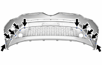
14. REMOVE FRONT BUMPER LOWER COVER
(a) for USA and Canada:
|
(1) Remove the 2 clips and 6 outside moulding retainers. |
|

|
(2) Disengage the claws and guides to remove the front bumper lower cover. |
|

|
(3) Remove the 8 grommets. |
|

(b) except USA and Canada:
|
(1) Remove the 2 clips and 8 outside moulding retainers. |
|
|
(2) Disengage the claws and guides to remove the front bumper lower cover. |
|

|
(3) Remove the 8 grommets. |
|

15. REMOVE NO. 1 RADIATOR GRILLE MOULDING (except USA and Canada)
|
(a) Disengage the claws to remove the No. 1 radiator grille moulding. HINT: Use the same procedure for the opposite side. |
|

16. REMOVE FRONT BUMPER SIDE RETAINER LH
|
(a) Remove the bolt. |
|

(b) Disengage the claw to remove the front bumper side retainer LH as shown in the illustration.

.png) |
Remove in this Direction |
17. REMOVE FRONT BUMPER SIDE RETAINER RH
HINT:
Use the same procedure as for the LH side.
18. REMOVE NO. 1 RADIATOR GRILLE RETAINER
(a) Disengage the claws to remove the No. 1 radiator grille retainer as shown in the illustration.

|
|
Remove in this Direction |
19. REMOVE NO. 1 RADIATOR TO SUPPORT SEAL
|
(a) Disengage the wire harness clamp. |
|

(b) Remove the 2 clips.
(c) Remove the No. 1 radiator to support seal as shown in the illustration.

|
|
Remove in this Direction |
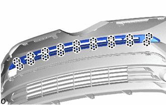
20. REMOVE FRONT BUMPER ENERGY ABSORBER
(a) for USA and Canada:
(1) Disengage the guides to remove the front bumper energy absorber as shown in the illustration.

|
|
Remove in this Direction |
(b) except USA and Canada:
(1) Disengage the guides to remove the front bumper energy absorber as shown in the illustration.

|
|
Remove in this Direction |
21. REMOVE FRONT ENERGY ABSORBER MOUNTING REINFORCEMENT (for USA and Canada)
|
(a) Disengage the claws to remove the front energy absorber mounting reinforcement. |
|

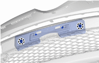
22. REMOVE LOWER FRONT BUMPER ABSORBER
(a) for USA and Canada:

|
|
Remove in this Direction |
(1) Disengage the guides to remove the lower front bumper energy absorber as shown in the illustration.
(b) except USA and Canada:
(1) Disengage the guides to remove the lower front bumper energy absorber as shown in the illustration.

|
|
Remove in this Direction |
23. REMOVE FRONT BUMPER REINFORCEMENT
(a) for USA and Canada:

(1) Disengage the wire harness clamps.
|
(2) Remove the 6 bolts. |
|

(3) Disengage the guides to remove the front bumper reinforcement.
(b) except USA and Canada:
|
(1) Disengage the wire harness clamps. |
|

|
(2) Remove the 6 bolts. |
|

(3) Disengage the guides to remove the front bumper reinforcement.
24. REMOVE FRONT SIDE MEMBER BRACKET SUB-ASSEMBLY LH
(a) for USA and Canada:
|
(1) Remove the 5 bolts. |
|

(2) Disengage the guides to remove the front side member bracket sub-assembly LH.
(b) except USA and Canada:
|
(1) Disengage the wire harness clamp. |
|

(2) Remove the 4 bolts.
(3) Disengage the guides to remove the front side member bracket sub-assembly LH.
25. REMOVE FRONT SIDE MEMBER BRACKET SUB-ASSEMBLY RH
(a) for USA and Canada:
|
(1) Remove the 4 bolts. |
|

(2) Disengage the guides to remove the front side member bracket sub-assembly RH.
(b) except USA and Canada:
HINT:
Use the same procedure as for the LH side.
26. REMOVE NO. 2 FRONT BUMPER REINFORCEMENT
|
(a) Remove the 2 nuts and No. 2 front bumper reinforcement. |
|

27. REMOVE FRONT BUMPER BRACKET LH
|
(a) Remove the 4 bolts and front bumper bracket LH. |
|

28. REMOVE FRONT BUMPER BRACKET RH
HINT:
Use the same procedure as for the LH side.
29. REMOVE NO. 1 RADIATOR AIR GUIDE LH
(a) Disengage the claw and guide to remove the No. 1 radiator air guide LH as shown in the illustration.

|
|
Remove in this Direction (1) |
.png) |
Remove in this Direction (2) |
30. REMOVE NO. 1 RADIATOR AIR GUIDE RH
(a) Disengage the claw and guide to remove the No. 1 radiator air guide RH as shown in the illustration.

|
|
Remove in this Direction (1) |
|
|
Remove in this Direction (2) |
 Removal
REMOVAL
PROCEDURE
1. REMOVE RADIATOR COVER
(a) Remove the 2 hood bumper cushions.
(b) Remove the 4 clips.
(c) Disengage the guides to re ...
 Installation
INSTALLATION
PROCEDURE
1. INSTALL FRONT BUMPER ASSEMBLY
(a) Move the front bumper assembly into position.
(b) w/ Toyota Safety Sense:
(1) Connect the connector.
(c) Temporarily install the front ...
Other materials:
Toyota CH-R Service Manual > Rear Door: Adjustment
ADJUSTMENT
CAUTION / NOTICE / HINT
*a
Centering Bolt
*b
Standard Bolt
HINT:
Use the same procedure for the RH side and LH side.
The following procedure is for the LH side.
Centering bolts are used to install the door hi ...
Toyota CH-R Service Manual > Instrument Panel Safety Pad: Removal
REMOVAL
CAUTION / NOTICE / HINT
The necessary procedures (adjustment, calibration, initialization, or registration)
that must be performed after parts are removed, installed, or replaced during the
instrument panel safety pad sub-assembly removal/installation are shown below.
Necessary Proced ...
Toyota C-HR (AX20) 2023-2025 Owner's Manual
Toyota CH-R Owners Manual
- For safety and security
- Instrument cluster
- Operation of each component
- Driving
- Interior features
- Maintenance and care
- When trouble arises
- Vehicle specifications
- For owners
Toyota CH-R Service Manual
- Introduction
- Maintenance
- Audio / Video
- Cellular Communication
- Navigation / Multi Info Display
- Park Assist / Monitoring
- Brake (front)
- Brake (rear)
- Brake Control / Dynamic Control Systems
- Brake System (other)
- Parking Brake
- Axle And Differential
- Drive Shaft / Propeller Shaft
- K114 Cvt
- 3zr-fae Battery / Charging
- Networking
- Power Distribution
- Power Assist Systems
- Steering Column
- Steering Gear / Linkage
- Alignment / Handling Diagnosis
- Front Suspension
- Rear Suspension
- Tire / Wheel
- Tire Pressure Monitoring
- Door / Hatch
- Exterior Panels / Trim
- Horn
- Lighting (ext)
- Mirror (ext)
- Window / Glass
- Wiper / Washer
- Door Lock
- Heating / Air Conditioning
- Interior Panels / Trim
- Lighting (int)
- Meter / Gauge / Display
- Mirror (int)
- Power Outlets (int)
- Pre-collision
- Seat
- Seat Belt
- Supplemental Restraint Systems
- Theft Deterrent / Keyless Entry

0.0108