Toyota CH-R Service Manual: Inspection
INSPECTION
PROCEDURE
1. INSPECT SHIFT LOCK CONTROL UNIT ASSEMBLY (w/o Smart Key System)
HINT:
If the results of the following inspections are as specified but a malfunction has occurred, replace the shift lock control unit assembly.
(a) Inspect the wire harness.
|
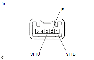
(1) Disconnect the shift lock control ECU connector. |
|

|
(2) Measure the voltage according to the value(s) in the table below. Standard Voltage:
If the result is not as specified, repair or replace the wire harness or connector. |
|

|
(3) Measure the resistance according to the value(s) in the table below. Standard Resistance:
If the result is not as specified, repair or replace the wire harness or connector. |
|

(b) Inspect the key interlock solenoid operation signal.
|
(1) Connect the shift lock control ECU connector. |
|
|
(2) Measure the voltage according to the value(s) in the table below. Standard Voltage:
If the result is not as specified, replace the shift lock control unit assembly. HINT: Do not disconnect the shift lock control ECU connector. |
|

(c) Inspect the shift lock solenoid.
|
(1) Disconnect the shift lock solenoid connector. |
|

|
(2) Measure the resistance according to the value(s) in the table below. Standard Resistance:
If the result is not as specified, replace the shift lock control unit assembly. |
|

2. INSPECT SHIFT LOCK CONTROL UNIT ASSEMBLY (w/ Smart Key System)
HINT:
If the results of the following inspections are as specified but a malfunction has occurred, replace the shift lock control unit assembly.
(a) Inspect the wire harness.
|
(1) Disconnect the shift lock control ECU connector. |
|
|
(2) Measure the voltage according to the value(s) in the table below. Standard Voltage:
If the result is not as specified, repair or replace the wire harness or connector. |
|

|
(3) Measure the resistance according to the value(s) in the table below. Standard Resistance:
If the result is not as specified, repair or replace the wire harness or connector. |
|

(b) Inspect the shift lock solenoid.
|
(1) Disconnect the shift lock solenoid connector. |
|
|
(2) Measure the resistance according to the value(s) in the table below. Standard Resistance:
If the result is not as specified, replace the shift lock control unit assembly. |
|
3. INSPECT TRANSMISSION CONTROL SWITCH (SHIFT LOCK CONTROL UNIT ASSEMBLY)
|
(a) Disconnect the connector from the shift lock control unit assembly. |
|

|
(b) Measure the resistance according to the value(s) in the table below. Standard Resistance:
If the result is not as specified, replace the shift lock control unit assembly. |
|
 Disassembly
DISASSEMBLY
PROCEDURE
1. REMOVE SHIFTING HOLE COVER SUB-ASSEMBLY
(a) Disengage the 4 guides and 6 claws to remove the shifting hole cover
sub-assembly from the upper console panel su ...
 Reassembly
REASSEMBLY
PROCEDURE
1. INSTALL SHIFT LEVER HOUSING BRACKET SUB-ASSEMBLY
(a) Engage the 4 claws to install the shift lever housing bracket sub-assembly
to the shift lock control unit ...
Other materials:
Toyota CH-R Service Manual > Safety Connect System: System Description
SYSTEM DESCRIPTION
DESCRIPTION
(a) Safety Connect performs ACN (Automatic Collision Notification), manual emergency
calling, stolen vehicle tracking and roadside assistance service by, audio and data
communications between the vehicle and call center through a cellular phone network.
As show ...
Toyota CH-R Service Manual > Pre-collision System: How To Proceed With Troubleshooting
CAUTION / NOTICE / HINT
HINT:
Use these procedures to troubleshoot the pre-collision system.
*: Use the Techstream.
PROCEDURE
1.
VEHICLE BROUGHT TO WORKSHOP
NEXT
2.
...
Toyota C-HR (AX20) 2023-2025 Owner's Manual
Toyota CH-R Owners Manual
- For safety and security
- Instrument cluster
- Operation of each component
- Driving
- Interior features
- Maintenance and care
- When trouble arises
- Vehicle specifications
- For owners
Toyota CH-R Service Manual
- Introduction
- Maintenance
- Audio / Video
- Cellular Communication
- Navigation / Multi Info Display
- Park Assist / Monitoring
- Brake (front)
- Brake (rear)
- Brake Control / Dynamic Control Systems
- Brake System (other)
- Parking Brake
- Axle And Differential
- Drive Shaft / Propeller Shaft
- K114 Cvt
- 3zr-fae Battery / Charging
- Networking
- Power Distribution
- Power Assist Systems
- Steering Column
- Steering Gear / Linkage
- Alignment / Handling Diagnosis
- Front Suspension
- Rear Suspension
- Tire / Wheel
- Tire Pressure Monitoring
- Door / Hatch
- Exterior Panels / Trim
- Horn
- Lighting (ext)
- Mirror (ext)
- Window / Glass
- Wiper / Washer
- Door Lock
- Heating / Air Conditioning
- Interior Panels / Trim
- Lighting (int)
- Meter / Gauge / Display
- Mirror (int)
- Power Outlets (int)
- Pre-collision
- Seat
- Seat Belt
- Supplemental Restraint Systems
- Theft Deterrent / Keyless Entry

0.0119