Toyota CH-R Service Manual: Installation
INSTALLATION
PROCEDURE
1. INSTALL BRAKE BOOSTER GASKET
(a) Install a new brake booster gasket to the brake booster assembly.
2. INSTALL BRAKE BOOSTER ASSEMBLY
(a) Temporarily install the brake booster assembly to the vehicle body.
NOTICE:
Do not apply excessive force to the brake lines or refrigerant lines.
(b) Temporarily install the clevis lock nut and brake master cylinder push rod clevis to the brake booster assembly.
NOTICE:
Fully tighten the clevis lock nut when adjusting the brake pedal height.
|
(c) Install the 4 nuts to secure the brake booster assembly. Torque: 12.7 N·m {130 kgf·cm, 9 ft·lbf} NOTICE: Tighten the 4 nuts in the order shown in the illustration. |
|

(d) Remove the protective tape.
(e) Engage the 2 clamps to install the fuel pipe to the fuel pipe clamp.
(f) Engage the 4 clamps to install the brake tube to the 2 brake tube clamps.
(g) Connect the vacuum warning switch connector.
3. CONNECT CHECK VALVE TO CONNECTOR TUBE HOSE
(a) Connect the check valve to connector tube hose to the brake booster assembly and slide the clip to secure it.
4. INSTALL DASH PANEL HEAT INSULATOR
|
(a) Temporarily install dash panel heat insulator to the vehicle body with the 2 nuts (A). |
|

|
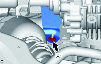
(b) Install the nut (B). Torque: 5.0 N·m {51 kgf·cm, 44 in·lbf} |
|
(c) Tighten the 2 nuts (A).
Torque:
5.0 N·m {51 kgf·cm, 44 in·lbf}
5. INSTALL NO. 1 ENGINE UNDER COVER
Click here
.gif)
6. INSTALL PUSH ROD PIN
Click here
7. INSTALL BRAKE PEDAL RETURN SPRING
Click here
8. INSTALL BRAKE MASTER CYLINDER SUB-ASSEMBLY
Click here
9. INSPECT AND ADJUST BRAKE PEDAL
Click here
 Reassembly
REASSEMBLY
PROCEDURE
1. INSTALL VACUUM WARNING SWITCH ASSEMBLY
(a) Install a new check valve grommet to the brake booster assembly.
(b) Install the vacuum sensor assembly to the brake b ...
 Brake Fluid
...
Other materials:
Toyota CH-R Service Manual > Can Communication System: Center Airbag Sensor Communication Stop Mode
DESCRIPTION
Detection Item
Symptom
Trouble Area
Center Airbag Sensor Communication Stop Mode
Any of the following conditions are met:
Communication stop for "Airbag" is indicated on the "Communication
Bu ...
Toyota CH-R Service Manual > Power Window Control System: Jam Protection Function does not Operate
DESCRIPTION
This symptom may occur for any of the power windows.
The jam protection function operates within a specified range during the manual
up or auto up operation.
CAUTION / NOTICE / HINT
NOTICE:
If a power window regulator motor assembly has been replaced with a
new one, in ...
Toyota C-HR (AX20) 2023-2025 Owner's Manual
Toyota CH-R Owners Manual
- For safety and security
- Instrument cluster
- Operation of each component
- Driving
- Interior features
- Maintenance and care
- When trouble arises
- Vehicle specifications
- For owners
Toyota CH-R Service Manual
- Introduction
- Maintenance
- Audio / Video
- Cellular Communication
- Navigation / Multi Info Display
- Park Assist / Monitoring
- Brake (front)
- Brake (rear)
- Brake Control / Dynamic Control Systems
- Brake System (other)
- Parking Brake
- Axle And Differential
- Drive Shaft / Propeller Shaft
- K114 Cvt
- 3zr-fae Battery / Charging
- Networking
- Power Distribution
- Power Assist Systems
- Steering Column
- Steering Gear / Linkage
- Alignment / Handling Diagnosis
- Front Suspension
- Rear Suspension
- Tire / Wheel
- Tire Pressure Monitoring
- Door / Hatch
- Exterior Panels / Trim
- Horn
- Lighting (ext)
- Mirror (ext)
- Window / Glass
- Wiper / Washer
- Door Lock
- Heating / Air Conditioning
- Interior Panels / Trim
- Lighting (int)
- Meter / Gauge / Display
- Mirror (int)
- Power Outlets (int)
- Pre-collision
- Seat
- Seat Belt
- Supplemental Restraint Systems
- Theft Deterrent / Keyless Entry

0.0098