Toyota CH-R Service Manual: Removal
REMOVAL
CAUTION / NOTICE / HINT
HINT:
- Use the same procedure for the RH side and LH side.
- The following procedure is for the LH side.
- The front speed sensor rotor is a component of the front axle hub sub-assembly. If the front speed sensor rotor is malfunctioning, replace the front axle hub sub-assembly.
PROCEDURE
1. REMOVE FRONT WHEEL
Click here
.gif)
2. REMOVE ROCKER PANEL MOULDING
Click here
3. SEPARATE FRONT FENDER LINER
|
(a) Remove the 4 screws. |
|

|
(b) Remove the 3 clips and separate the front fender liner. |
|

4. REMOVE FRONT SPEED SENSOR
(a) Turn back the front fender liner.
|
(b) Disconnect the connector. |
|

(c) Disengage the clamp from the vehicle body.
|
(d) Disengage the clamp from the vehicle body. |
|

(e) Remove the 2 bolts and separate the 2 front speed sensor clamps.
|
(f) Remove the bolt and separate the front flexible hose and front speed sensor clamp from the front shock absorber assembly. |
|
(g) Disengage the clamp from the front shock absorber assembly.
|
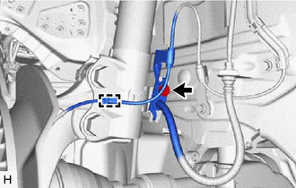
(h) Remove the bolt and front speed sensor from the steering knuckle. NOTICE:
|
|

 Components
COMPONENTS
ILLUSTRATION
*1
FRONT FENDER LINER
*2
FRONT SPEED SENSOR
*3
FRONT FLEXIBLE HOSE
-
-
...
 Installation
INSTALLATION
CAUTION / NOTICE / HINT
HINT:
Use the same procedure for the RH side and LH side.
The following procedure is for the LH side.
The front speed sensor rotor is a componen ...
Other materials:
Toyota CH-R Service Manual > Blower Unit(for Valeo Made): Components
COMPONENTS
ILLUSTRATION
*A
for Dual Type
*B
for Single Type
*C
w/ PTC Heater
-
-
*1
BLOWER ASSEMBLY
*2
NO. 2 AIR DUCT
*3
NO. ...
Toyota CH-R Service Manual > Console Box Light: Components
COMPONENTS
ILLUSTRATION
*1
COWL SIDE TRIM BOARD LH
*2
FRONT DOOR SCUFF PLATE LH
*3
INSTRUMENT CLUSTER FINISH PANEL GARNISH ASSEMBLY
*4
INSTRUMENT PANEL BOX ASSEMBLY
*5
INSTRU ...
Toyota C-HR (AX20) 2023-2025 Owner's Manual
Toyota CH-R Owners Manual
- For safety and security
- Instrument cluster
- Operation of each component
- Driving
- Interior features
- Maintenance and care
- When trouble arises
- Vehicle specifications
- For owners
Toyota CH-R Service Manual
- Introduction
- Maintenance
- Audio / Video
- Cellular Communication
- Navigation / Multi Info Display
- Park Assist / Monitoring
- Brake (front)
- Brake (rear)
- Brake Control / Dynamic Control Systems
- Brake System (other)
- Parking Brake
- Axle And Differential
- Drive Shaft / Propeller Shaft
- K114 Cvt
- 3zr-fae Battery / Charging
- Networking
- Power Distribution
- Power Assist Systems
- Steering Column
- Steering Gear / Linkage
- Alignment / Handling Diagnosis
- Front Suspension
- Rear Suspension
- Tire / Wheel
- Tire Pressure Monitoring
- Door / Hatch
- Exterior Panels / Trim
- Horn
- Lighting (ext)
- Mirror (ext)
- Window / Glass
- Wiper / Washer
- Door Lock
- Heating / Air Conditioning
- Interior Panels / Trim
- Lighting (int)
- Meter / Gauge / Display
- Mirror (int)
- Power Outlets (int)
- Pre-collision
- Seat
- Seat Belt
- Supplemental Restraint Systems
- Theft Deterrent / Keyless Entry

0.0104