Toyota CH-R Service Manual: Removal
REMOVAL
CAUTION / NOTICE / HINT
The necessary procedures (adjustment, calibration, initialization, or registration) that must be performed after parts are removed, installed, or replaced during the front seat airbag assembly removal/installation are shown below.
Necessary Procedure After Parts Removed/Installed/Replaced|
Replacement Part or Procedure |
Necessary Procedures |
Effects / Inoperative when not performed |
Link |
|---|---|---|---|
|
Disconnect cable from negative battery terminal |
Initialize back door lock |
Power door lock control system |
|
|
Memorize steering angle neutral point |
Lane departure alert system (w/ Steering Control) |
|
|
|
Pre-collision system |
CAUTION:
- Be sure to read Precaution thoroughly before servicing.
Click here
.gif)
- Wear protective gloves. Sharp areas on the parts may injure your hands.
.png)
NOTICE:
If a front seat airbag assembly has been deployed, replace the front seat airbag assembly, front seatback frame sub-assembly, separate type front seatback pad and separate type front seatback cover with the necessary parts in accordance with the extent of the collision damage.
HINT:
- Use the same procedure for the driver side and front passenger side.
- The procedure listed below is for the driver side.
PROCEDURE
1. REMOVE SEPARATE TYPE FRONT SEATBACK COVER WITH PAD
Click here
2. REMOVE FRONT SEAT AIRBAG ASSEMBLY
CAUTION:
When storing the front seat airbag assembly, keep the airbag deployment side facing upward.
.png) |
Deployment Side |
|
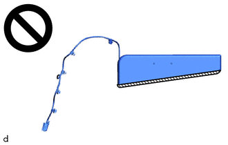
(a) Disengage the clamp. |
|

(b) Remove the 2 nuts and front seat airbag assembly.
NOTICE:
- Do not reuse the nuts.
- Make sure that the front seatback frame sub-assembly is not deformed. If it is deformed, replace it with a new one.
 On-vehicle Inspection
ON-VEHICLE INSPECTION
CAUTION / NOTICE / HINT
CAUTION:
Be sure to correctly follow the removal and installation procedures for the front
seat airbag assemblies.
PROCEDURE
1. INSPECT FRONT SEAT ...
 Disposal
DISPOSAL
CAUTION / NOTICE / HINT
CAUTION:
Before performing pre-disposal deployment of any SRS part, review and closely
follow all applicable environmental and hazardous material regulations. Pre ...
Other materials:
Toyota CH-R Owners Manual > Before driving: Trailer towing
Toyota does not recommend towing a trailer with your vehicle.
Toyota also does not recommend the installation of a tow hitch or
the use of a tow hitch carrier for a wheelchair, scooter, bicycle, etc. Your vehicle
is not designed for trailer towing or for the use of tow hitch mounted carriers. ...
Toyota CH-R Service Manual > Seat Belt Warning System(w/ Occupant Classification System): On-vehicle Inspection
ON-VEHICLE INSPECTION
PROCEDURE
1. INSPECT DRIVER SEAT BELT WARNING LIGHT
HINT:
The seat belt warning light on the combination meter assembly is used for both
the driver seat and front passenger seat.
(a) Turn the ignition switch to ON.
(b) When the driver seat belt is not fastened, check th ...
Toyota C-HR (AX20) 2023-2025 Owner's Manual
Toyota CH-R Owners Manual
- For safety and security
- Instrument cluster
- Operation of each component
- Driving
- Interior features
- Maintenance and care
- When trouble arises
- Vehicle specifications
- For owners
Toyota CH-R Service Manual
- Introduction
- Maintenance
- Audio / Video
- Cellular Communication
- Navigation / Multi Info Display
- Park Assist / Monitoring
- Brake (front)
- Brake (rear)
- Brake Control / Dynamic Control Systems
- Brake System (other)
- Parking Brake
- Axle And Differential
- Drive Shaft / Propeller Shaft
- K114 Cvt
- 3zr-fae Battery / Charging
- Networking
- Power Distribution
- Power Assist Systems
- Steering Column
- Steering Gear / Linkage
- Alignment / Handling Diagnosis
- Front Suspension
- Rear Suspension
- Tire / Wheel
- Tire Pressure Monitoring
- Door / Hatch
- Exterior Panels / Trim
- Horn
- Lighting (ext)
- Mirror (ext)
- Window / Glass
- Wiper / Washer
- Door Lock
- Heating / Air Conditioning
- Interior Panels / Trim
- Lighting (int)
- Meter / Gauge / Display
- Mirror (int)
- Power Outlets (int)
- Pre-collision
- Seat
- Seat Belt
- Supplemental Restraint Systems
- Theft Deterrent / Keyless Entry

0.0103