Toyota CH-R Service Manual: Removal
REMOVAL
CAUTION / NOTICE / HINT
The necessary procedures (adjustment, calibration, initialization, or registration) that must be performed after parts are removed, installed, or replaced during the airbag sensor assembly removal/installation are shown below.
Necessary Procedure After Parts Removed/Installed/Replaced|
Replacement Part or Procedure |
Necessary Procedures |
Effects / Inoperative when not performed |
Link |
|---|---|---|---|
|
Disconnect cable from negative battery terminal |
Initialize back door lock |
Power door lock control system |
|
|
Memorize steering angle neutral point |
Lane departure alert system (w/ Steering Control) |
|
|
|
Pre-collision system |
|||
|
Replacement of the airbag sensor assembly |
|
|
|
|
Deterioration of fuel efficiency |
|
PROCEDURE
1. PRECAUTION
CAUTION:
Be sure to read Precaution thoroughly before servicing.
Click here .gif)
.png)
NOTICE:
After turning the ignition switch off, waiting time may be required before disconnecting the cable from the negative (-) battery terminal. Therefore, make sure to read the disconnecting the cable from the negative (-) battery terminal notices before proceeding with work.
Click here
2. DISCONNECT CABLE FROM NEGATIVE BATTERY TERMINAL
Click here
.png)
- Wait at least 90 seconds after disconnecting the cable from the negative (-) battery terminal to disable the SRS system.
- If an SRS part is accidentally deployed, it may cause a serious injury.
NOTICE:
When disconnecting the cable, some systems need to be initialized after the cable is reconnected.
Click here
3. REMOVE REAR CONSOLE BOX ASSEMBLY
Click here
4. REMOVE REAR NO. 2 AIR DUCT (w/ Rear Air Duct)
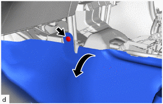
(a) Disengage the claws to remove the rear No. 2 air duct as shown in the illustration.

.png) |
Remove in this direction (1) |
.png) |
Remove in this direction (2) |
5. REMOVE AIRBAG SENSOR ASSEMBLY
(a) Check that the ignition switch off.
(b) Check that the cable is disconnected from the negative (-) battery terminal.
CAUTION:
Wait at least 90 seconds after disconnecting the cable from the negative (-) battery terminal to disable the SRS system.
|
(c) Remove the clip and turn back the front floor carpet assembly as shown in the illustration (for LH side). |
|
|
(d) Remove the clip and turn back the front floor carpet assembly as shown in the illustration (for RH side). |
|

(e) Disconnect the connectors from the airbag sensor assembly as shown in the illustration.
NOTICE:
When disconnecting any airbag connector, take care not to damage the airbag wire harness.

|
|
Release in this direction |
|
(f) Remove the 3 bolts and airbag sensor assembly. |
|
.png)
 Installation
INSTALLATION
PROCEDURE
1. INSTALL AIRBAG SENSOR ASSEMBLY
(a) Check that the ignition switch off.
(b) Check that the cable is disconnected from the negative (-) battery terminal.
CAUTION:
Wait at ...

Other materials:
Toyota CH-R Owners Manual > Do-it-yourself maintenance: Hood
Release the lock from the inside of the vehicle to open the hood.
1. Pull the hood lock release lever.
The hood will pop up slightly.
2. Move the auxiliary catch lever to side direction and lift the hood.
3. Hold the hood open by inserting the support rod into the slot.
WARNING� ...
Toyota CH-R Service Manual > Immobiliser System(w/o Smart Key System): Push Switch / Key Unlock Warning Switch Malfunction (B2780)
DESCRIPTION
This DTC is stored if the transponder key ECU assembly does not detect that the
unlock warning switch assembly is on even when the ignition switch is ON.
DTC No.
Detection Item
DTC Detection Condition
Trouble Area
Note
...
Toyota C-HR (AX20) 2023-2025 Owner's Manual
Toyota CH-R Owners Manual
- For safety and security
- Instrument cluster
- Operation of each component
- Driving
- Interior features
- Maintenance and care
- When trouble arises
- Vehicle specifications
- For owners
Toyota CH-R Service Manual
- Introduction
- Maintenance
- Audio / Video
- Cellular Communication
- Navigation / Multi Info Display
- Park Assist / Monitoring
- Brake (front)
- Brake (rear)
- Brake Control / Dynamic Control Systems
- Brake System (other)
- Parking Brake
- Axle And Differential
- Drive Shaft / Propeller Shaft
- K114 Cvt
- 3zr-fae Battery / Charging
- Networking
- Power Distribution
- Power Assist Systems
- Steering Column
- Steering Gear / Linkage
- Alignment / Handling Diagnosis
- Front Suspension
- Rear Suspension
- Tire / Wheel
- Tire Pressure Monitoring
- Door / Hatch
- Exterior Panels / Trim
- Horn
- Lighting (ext)
- Mirror (ext)
- Window / Glass
- Wiper / Washer
- Door Lock
- Heating / Air Conditioning
- Interior Panels / Trim
- Lighting (int)
- Meter / Gauge / Display
- Mirror (int)
- Power Outlets (int)
- Pre-collision
- Seat
- Seat Belt
- Supplemental Restraint Systems
- Theft Deterrent / Keyless Entry

0.0097