Toyota CH-R Service Manual: Power Outlet Socket
Components
COMPONENTS
ILLUSTRATION

|
*1 |
NO. 1 POWER OUTLET SOCKET ASSEMBLY |
*2 |
NO. 1 POWER OUTLET SOCKET COVER |
Removal
REMOVAL
PROCEDURE
1. REMOVE NO. 2 CONSOLE BOX CUP HOLDER
Click here .gif)
2. REMOVE NO. 1 POWER OUTLET SOCKET ASSEMBLY
(a) Disconnect the connector.
(b) Using a screwdriver with its tip wrapped in protective tape, disengage the claw to remove the No. 1 power outlet socket assembly as shown in the illustration.

|
*a |
Protective Tape |
.png) |
Remove in this Direction |
3. REMOVE NO. 1 POWER OUTLET SOCKET COVER
(a) Disengage the claws to remove the No. 1 power outlet socket cover as shown in the illustration.

|
|
Remove in this Direction |
Installation
INSTALLATION
PROCEDURE
1. INSTALL NO. 1 POWER OUTLET SOCKET COVER
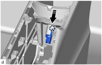
(a) Engage the claws to install the No. 1 power outlet socket cover as shown in the illustration.
.png) |
Install in this Direction |
2. INSTALL NO. 1 POWER OUTLET SOCKET ASSEMBLY
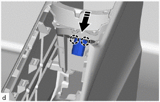
(a) Engage the claw to install the No. 1 power outlet socket assembly as shown in the illustration.
|
|
Install in this Direction |
(b) Connect the connector.
3. INSTALL NO. 2 CONSOLE BOX CUP HOLDER
Click here .gif)

 Pre-collision
...
Other materials:
Toyota CH-R Service Manual > Seat Belt Warning System(w/o Occupant Classification System): Driver Side Seat Belt Warning Light does not Operate
DESCRIPTION
The combination meter assembly blinks or turns off the seat belt warning light
on the combination meter assembly in accordance with the state of the front seat
inner belt assembly (driver seat).
WIRING DIAGRAM
CAUTION / NOTICE / HINT
NOTICE:
The seat belt warning syste ...
Toyota CH-R Service Manual > Door Control Transmitter(w/o Smart Key System): Installation
INSTALLATION
CAUTION / NOTICE / HINT
NOTICE:
Take extra care when handling these precision electronic components.
PROCEDURE
1. INSTALL TRANSMITTER BATTERY
(a) Install a new transmitter battery with the positive (+) side facing upward,
as shown in the illustration.
Inst ...
Toyota CH-R Owners Manual
- For safety and security
- Instrument cluster
- Operation of each component
- Driving
- Interior features
- Maintenance and care
- When trouble arises
- Vehicle specifications
- For owners
Toyota CH-R Service Manual
- Introduction
- Maintenance
- Audio / Video
- Cellular Communication
- Navigation / Multi Info Display
- Park Assist / Monitoring
- Brake (front)
- Brake (rear)
- Brake Control / Dynamic Control Systems
- Brake System (other)
- Parking Brake
- Axle And Differential
- Drive Shaft / Propeller Shaft
- K114 Cvt
- 3zr-fae Battery / Charging
- Networking
- Power Distribution
- Power Assist Systems
- Steering Column
- Steering Gear / Linkage
- Alignment / Handling Diagnosis
- Front Suspension
- Rear Suspension
- Tire / Wheel
- Tire Pressure Monitoring
- Door / Hatch
- Exterior Panels / Trim
- Horn
- Lighting (ext)
- Mirror (ext)
- Window / Glass
- Wiper / Washer
- Door Lock
- Heating / Air Conditioning
- Interior Panels / Trim
- Lighting (int)
- Meter / Gauge / Display
- Mirror (int)
- Power Outlets (int)
- Pre-collision
- Seat
- Seat Belt
- Supplemental Restraint Systems
- Theft Deterrent / Keyless Entry

0.0102