Toyota CH-R Service Manual: Reassembly
REASSEMBLY
PROCEDURE
1. INSTALL BLOWER RESISTOR (for Single Type)
(a) Engage the guides and install the blower resistor as shown in the illustration.

.png) |
Install in this Direction |
2. INSTALL AIR FILTER SUB-ASSEMBLY (for Single Type)
|
(a) Engage the guides to Install the air filter sub-assembly. |
|
.png)
(b) Install the 2 screws.
3. INSTALL NO. 1 BLOWER DAMPER SERVO SUB-ASSEMBLY (for Single Type)
(a) Install the No. 1 blower damper servo sub-assembly as shown in the illustration.

|
|
Install in this Direction |
(b) Turn the No. 1 blower damper servo sub-assembly to engage the claw as shown in the illustration.

|
|
Install in this Direction |
|
(c) Connect the damper servo link. |
|
.png)
4. INSTALL BLOWER RESISTOR (for Dual Type)
(a) Engage the guides and install the blower resistor as shown in the illustration.

|
|
Install in this Direction |
5. INSTALL AIR FILTER SUB-ASSEMBLY (for Dual Type)
|
(a) Install the air filter sub-assembly with the 4 screws. |
|
.png)
6. INSTALL NO. 1 BLOWER DAMPER SERVO SUB-ASSEMBLY (for Dual Type)
(a) Install the No. 1 blower damper servo sub-assembly as shown in the illustration.

|
|
Install in this Direction |
(b) Turn the No. 1 blower damper servo sub-assembly to engage the claw as shown in the illustration.

|
|
Install in this Direction |
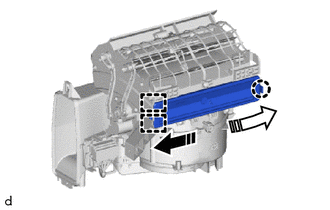
7. INSTALL BLOWER MOTOR WITH FAN SUB-ASSEMBLY (for Single Type)
|
(a) Install the blower motor with fan sub-assembly with the 3 screws. NOTICE: Replace the blower motor with fan sub-assembly if it has been dropped or subjected to a severe impact. |
|
.png)
(b) Connect the connector.
8. INSTALL CLEAN AIR FILTER
(a) Install the clean air filter as shown in the illustration.

|
|
Install in this Direction |
NOTICE:
Make sure that the "UP" mark is facing the correct direction before installing the clean air filter.
9. INSTALL AIR FILTER COVER PLATE
(a) Engage the guide and claw to install the air filter cover plate as shown in the illustration.
|
|
Install in this Direction (1) |
.png) |
Install in this Direction (2) |
 Installation
INSTALLATION
PROCEDURE
1. INSTALL BLOWER ASSEMBLY
(a) Engage the guides to install the air conditioning radiator assembly.
(b) Install th ...

Other materials:
Toyota CH-R Service Manual > Solar Sensor: Installation
INSTALLATION
PROCEDURE
1. INSTALL AUTOMATIC LIGHT CONTROL SENSOR
(a) Engage the claws to install the automatic light control sensor.
(b) Connect the connector.
2. INSTALL DEFROSTER NOZZLE ASSEMBLY
Click here
3. INSTALL INSTRUM ...
Toyota CH-R Service Manual > Wireless Door Lock Control System(w/o Smart Key System): Problem Symptoms Table
PROBLEM SYMPTOMS TABLE
HINT:
Use the table below to help determine the cause of problem symptoms.
If multiple suspected areas are listed, the potential causes of the symptoms
are listed in order of probability in the "Suspected Area" column of the
table. Check each sy ...
Toyota C-HR (AX20) 2023-2025 Owner's Manual
Toyota CH-R Owners Manual
- For safety and security
- Instrument cluster
- Operation of each component
- Driving
- Interior features
- Maintenance and care
- When trouble arises
- Vehicle specifications
- For owners
Toyota CH-R Service Manual
- Introduction
- Maintenance
- Audio / Video
- Cellular Communication
- Navigation / Multi Info Display
- Park Assist / Monitoring
- Brake (front)
- Brake (rear)
- Brake Control / Dynamic Control Systems
- Brake System (other)
- Parking Brake
- Axle And Differential
- Drive Shaft / Propeller Shaft
- K114 Cvt
- 3zr-fae Battery / Charging
- Networking
- Power Distribution
- Power Assist Systems
- Steering Column
- Steering Gear / Linkage
- Alignment / Handling Diagnosis
- Front Suspension
- Rear Suspension
- Tire / Wheel
- Tire Pressure Monitoring
- Door / Hatch
- Exterior Panels / Trim
- Horn
- Lighting (ext)
- Mirror (ext)
- Window / Glass
- Wiper / Washer
- Door Lock
- Heating / Air Conditioning
- Interior Panels / Trim
- Lighting (int)
- Meter / Gauge / Display
- Mirror (int)
- Power Outlets (int)
- Pre-collision
- Seat
- Seat Belt
- Supplemental Restraint Systems
- Theft Deterrent / Keyless Entry

0.0112