Toyota CH-R Service Manual: Disassembly
DISASSEMBLY
PROCEDURE
1. PRECAUTION
NOTICE:
Make sure to perform initialization after replacing the No. 1 blower damper servo sub-assembly. If initialization is not performed, the air conditioner unit assembly will not perform properly as the air conditioning amplifier assembly will not be able to recognize the position of the No. 1 blower damper servo sub-assembly.
2. REMOVE AIR FILTER COVER PLATE
(a) Disengage the claw and guides as shown in the illustration to remove the air filter cover plate.

.png) |
Remove in this Direction (1) |
.png) |
Remove in this Direction (2) |
3. REMOVE CLEAN AIR FILTER
(a) Remove the air filter sub-assembly as shown in the illustration.

|
|
Remove in this Direction |
|
(b) Disengage the guides to remove the clean air filter from the cooling unit parts. |
|
.png)
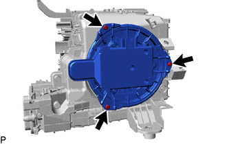
4. REMOVE BLOWER MOTOR WITH FAN SUB-ASSEMBLY
|
(a) Remove the 3 screws and the blower motor with fan sub-assembly. |
|
5. REMOVE NO. 1 BLOWER DAMPER SERVO SUB-ASSEMBLY
|
(a) Remove the 2 screws and the No. 1 blower damper servo sub-assembly. |
|

 Components
COMPONENTS
ILLUSTRATION
*1
BLOWER ASSEMBLY
*2
NO. 2 AIR DUCT
●
Non-reusable part
-
-
ILLUS ...
 Removal
REMOVAL
CAUTION / NOTICE / HINT
The necessary procedures (adjustment, calibration, initialization or registration)
that must be performed after parts are removed and installed, or replaced during ...
Other materials:
Toyota CH-R Service Manual > Rear Disc Brake Pad(for Tmmt Made): Removal
REMOVAL
CAUTION / NOTICE / HINT
HINT:
The following procedure is for the LH side.
Use the same procedure for the RH side and LH side.
PROCEDURE
1. PRECAUTION
Click here
2. REMOVE REAR WHEEL
Click here
3. PERFORM REAR BRAKE PAD REPLACEMENT MODE
Click here
4. D ...
Toyota CH-R Service Manual > Front Evaporator Temperature Sensor(for Valeo Made): Installation
INSTALLATION
PROCEDURE
1. INSTALL NO. 1 COOLER THERMISTOR
(a) Install the No. 1 cooler thermistor.
HINT:
Install the No. 1 cooler thermistor in the same area as the one that was previously
installed.
2. INSTALL NO. 1 COOLER EVAPORATOR SUB-ASSEMBLY
Click here
3. INSTALL RADIATOR CASE SU ...
Toyota C-HR (AX20) 2023-2025 Owner's Manual
Toyota CH-R Owners Manual
- For safety and security
- Instrument cluster
- Operation of each component
- Driving
- Interior features
- Maintenance and care
- When trouble arises
- Vehicle specifications
- For owners
Toyota CH-R Service Manual
- Introduction
- Maintenance
- Audio / Video
- Cellular Communication
- Navigation / Multi Info Display
- Park Assist / Monitoring
- Brake (front)
- Brake (rear)
- Brake Control / Dynamic Control Systems
- Brake System (other)
- Parking Brake
- Axle And Differential
- Drive Shaft / Propeller Shaft
- K114 Cvt
- 3zr-fae Battery / Charging
- Networking
- Power Distribution
- Power Assist Systems
- Steering Column
- Steering Gear / Linkage
- Alignment / Handling Diagnosis
- Front Suspension
- Rear Suspension
- Tire / Wheel
- Tire Pressure Monitoring
- Door / Hatch
- Exterior Panels / Trim
- Horn
- Lighting (ext)
- Mirror (ext)
- Window / Glass
- Wiper / Washer
- Door Lock
- Heating / Air Conditioning
- Interior Panels / Trim
- Lighting (int)
- Meter / Gauge / Display
- Mirror (int)
- Power Outlets (int)
- Pre-collision
- Seat
- Seat Belt
- Supplemental Restraint Systems
- Theft Deterrent / Keyless Entry

0.0099