Toyota CH-R Service Manual: Ambient Temperature Sensor
Components
COMPONENTS
ILLUSTRATION

|
*1 |
THERMISTOR ASSEMBLY |
- |
- |
Removal
REMOVAL
PROCEDURE
1. REMOVE FRONT BUMPER ASSEMBLY
Click here
.gif)
2. REMOVE THERMISTOR ASSEMBLY
|
(a) Disconnect the connector. |
|
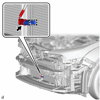
(b) Disengage the clamp to remove the thermistor assembly.
Inspection
INSPECTION
PROCEDURE
1. INSPECT THERMISTOR ASSEMBLY
(a) Check the resistance.
|
(1) Measure the resistance according to the value(s) in the table below. Standard resistance:
NOTICE:
HINT: As the temperature increases, the resistance decreases (see the graph). If the specified condition is not met, replace the thermistor assembly. |
|

Installation
INSTALLATION
PROCEDURE
1. INSTALL THERMISTOR ASSEMBLY
|
(a) Engage the clamp to install the thermistor assembly. |
|
.png)
(b) Connect the connector.
2. INSTALL FRONT BUMPER ASSEMBLY
Click here
.gif)
 Installation
INSTALLATION
PROCEDURE
1. INSTALL LOWER DEFROSTER NOZZLE ASSEMBLY
(a) Engage the claws to install the lower defroster nozzle assembly.
2. ...
 Blower Resistor
Components
COMPONENTS
ILLUSTRATION
*A
for Single Type
-
-
*1
BLOWER RESISTOR
*2
NO. 2 INSTRUMENT PA ...
Other materials:
Toyota CH-R Service Manual > Condenser: Removal
REMOVAL
CAUTION / NOTICE / HINT
The necessary procedures (adjustment, calibration, initialization, or registration)
that must be performed after parts are removed, installed, or replaced during the
condenser removal/installation are shown below.
Necessary Procedure After Parts Removed/Install ...
Toyota CH-R Service Manual > Airbag System: Precaution
PRECAUTION
HINT:
In the airbag system, the parts listed below are collectively referred to as
the airbag sensors.
Airbag sensor assembly
Front airbag sensor
Door side airbag sensors
No. 1 side airbag sensor
Floor side airbag sensor
No. 2 side airbag sensor
...
Toyota CH-R Owners Manual
- For safety and security
- Instrument cluster
- Operation of each component
- Driving
- Interior features
- Maintenance and care
- When trouble arises
- Vehicle specifications
- For owners
Toyota CH-R Service Manual
- Introduction
- Maintenance
- Audio / Video
- Cellular Communication
- Navigation / Multi Info Display
- Park Assist / Monitoring
- Brake (front)
- Brake (rear)
- Brake Control / Dynamic Control Systems
- Brake System (other)
- Parking Brake
- Axle And Differential
- Drive Shaft / Propeller Shaft
- K114 Cvt
- 3zr-fae Battery / Charging
- Networking
- Power Distribution
- Power Assist Systems
- Steering Column
- Steering Gear / Linkage
- Alignment / Handling Diagnosis
- Front Suspension
- Rear Suspension
- Tire / Wheel
- Tire Pressure Monitoring
- Door / Hatch
- Exterior Panels / Trim
- Horn
- Lighting (ext)
- Mirror (ext)
- Window / Glass
- Wiper / Washer
- Door Lock
- Heating / Air Conditioning
- Interior Panels / Trim
- Lighting (int)
- Meter / Gauge / Display
- Mirror (int)
- Power Outlets (int)
- Pre-collision
- Seat
- Seat Belt
- Supplemental Restraint Systems
- Theft Deterrent / Keyless Entry

0.0094