Toyota CH-R Service Manual: Removal
REMOVAL
CAUTION / NOTICE / HINT
The necessary procedures (adjustment, calibration, initialization, or registration) that must be performed after parts are removed, installed, or replaced during the condenser removal/installation are shown below.
Necessary Procedure After Parts Removed/Installed/Replaced|
Replacement Part or Procedure |
Necessary Procedures |
Effects / Inoperative when not performed |
Link |
|---|---|---|---|
|
Disconnect cable from negative battery terminal |
Memorize steering angle neutral point |
Lane departure alert system (w/ Steering Control) |
|
|
Pre-collision system |
|||
|
Initialize back door lock |
Power door lock control system |
|
PROCEDURE
1. RECOVER REFRIGERANT FROM REFRIGERATION SYSTEM (for HFC-134a(R134a))
Click here
.gif)
2. RECOVER REFRIGERANT FROM REFRIGERATION SYSTEM (for HFO-1234yf(R1234yf))
Click here
3. REMOVE HEADLIGHT ASSEMBLY LH (for Halogen Headlight)
Click here
4. REMOVE HEADLIGHT ASSEMBLY LH (for LED Headlight)
Click here
5. REMOVE HEADLIGHT ASSEMBLY RH (for Halogen Headlight)
HINT:
Use the same procedure as for the LH side.
6. REMOVE HEADLIGHT ASSEMBLY RH (for LED Headlight)
HINT:
Use the same procedure as for the LH side.
7. REMOVE NO. 1 AIR CLEANER INLET
Click here
8. REMOVE FRONT BUMPER UPPER REINFORCEMENT SUB-ASSEMBLY
Click here
9. REMOVE NO. 1 RADIATOR GRILLE RETAINER
Click here
10. REMOVE NO. 1 RADIATOR TO SUPPORT SEAL
Click here
11. REMOVE HOOD LOCK NUT CAP
Click here
12. REMOVE HOOD LOCK ASSEMBLY
- w/ Engine Hood Courtesy Switch:
Click here
- w/o Engine Hood Courtesy Switch:
Click here
13. REMOVE UPPER RADIATOR SUPPORT SUB-ASSEMBLY
Click here
14. REMOVE NO. 2 RADIATOR AIR GUIDE
Click here
15. REMOVE FRONT BUMPER ENERGY ABSORBER
Click here
16. REMOVE FRONT BUMPER REINFORCEMENT
Click here
17. REMOVE NO. 1 RADIATOR AIR GUIDE LH
Click here
18. REMOVE NO. 1 RADIATOR AIR GUIDE RH
Click here
19. DISCONNECT DISCHARGE HOSE SUB-ASSEMBLY
|
(a) Remove the bolt to disconnect the discharge hose sub-assembly from the cooler condenser assembly. |
|
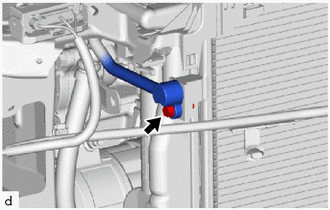
(b) Remove the O-ring from the discharge hose sub-assembly.
NOTICE:
Seal the openings of the disconnected parts using vinyl tape to prevent entry of moisture and foreign matter.
20. DISCONNECT COOLER REFRIGERANT LIQUID PIPE A (for VALEO Made)
|
(a) Remove the bolt to disconnect the cooler refrigerant liquid pipe A from the cooler condenser assembly. |
|
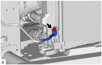
(b) Remove the O-ring from the cooler refrigerant liquid pipe A.
NOTICE:
Seal the openings of the disconnected parts using vinyl tape to prevent entry of moisture and foreign matter.
21. DISCONNECT COOLER REFRIGERANT LIQUID PIPE A (for DENSO Made)
(a) While pressing the end of the cooler refrigerant liquid pipe A into the end of the cooler condenser assembly, use pliers to squeeze together both sides of the piping clamp until it breaks apart.

|
*1 |
Cooler Refrigerant Liquid Pipe A |
*2 |
Cooler Condenser Assembly |
|
*3 |
Piping Clamp |
- |
- |
|
*a |
Press In |
- |
- |
NOTICE:
- If any foreign matter is adhered to the connecting part, brush it off or use compressed air to remove it.
- Make sure that fragments of the piping clamp do not enter the piping.
(b) Disconnect the cooler refrigerant liquid pipe A.
NOTICE:
Clean off any foreign matter near the ends of the cooler refrigerant liquid pipe A and cooler condenser assembly.
(c) Remove the 2 O-rings from the cooler refrigerant liquid pipe A.
NOTICE:
Wrap the open ends of the separated cooler condenser assembly and cooler refrigerant liquid pipe A accessory assembly with vinyl tape to prevent entry of moisture and foreign matter.
(d) Remove the piping clamp.
22. REMOVE COOLER CONDENSER ASSEMBLY
(a) Disengage the claws and guides to remove the cooler condenser assembly as shown in the illustration.
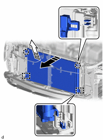
.png) |
Remove in this Direction (1) |
.png) |
Remove in this Direction (2) |
NOTICE:
Do not damage the cooler condenser assembly or radiator assembly when removing the cooler condenser assembly.
 On-vehicle Inspection
ON-VEHICLE INSPECTION
PROCEDURE
1. INSPECT COOLER CONDENSER ASSEMBLY
(a) If the cooler condenser assembly fins are dirty, clean them with water and
dry them with compressed air.
NOTICE:
Do not ...
 Disassembly
DISASSEMBLY
PROCEDURE
1. REMOVE COOLER DRYER (for VALEO Made)
(a) Using a T55 "TORX" socket wrench, remove the cap from the modulator.
...
Other materials:
Toyota CH-R Service Manual > Airbag System: Center Airbag Sensor Assembly Malfunction (B1000/31)
DESCRIPTION
The airbag sensor assembly consists of the acceleration sensor, safing sensor,
drive circuit, diagnosis circuit, ignition control, etc.
If the airbag sensor assembly receives signals from the acceleration sensor and
pressure sensor, it determines whether the airbags and pretensione ...
Toyota CH-R Service Manual > Radio Antenna Cord: Installation
INSTALLATION
PROCEDURE
1. INSTALL NO. 3 ANTENNA CORD SUB-ASSEMBLY
(a) w/o Manual (SOS) Switch
(1) Engage the clamp and guide to temporarily install the No. 3 antenna
cord sub-assembly.
*A
...
Toyota CH-R Owners Manual
- For safety and security
- Instrument cluster
- Operation of each component
- Driving
- Interior features
- Maintenance and care
- When trouble arises
- Vehicle specifications
- For owners
Toyota CH-R Service Manual
- Introduction
- Maintenance
- Audio / Video
- Cellular Communication
- Navigation / Multi Info Display
- Park Assist / Monitoring
- Brake (front)
- Brake (rear)
- Brake Control / Dynamic Control Systems
- Brake System (other)
- Parking Brake
- Axle And Differential
- Drive Shaft / Propeller Shaft
- K114 Cvt
- 3zr-fae Battery / Charging
- Networking
- Power Distribution
- Power Assist Systems
- Steering Column
- Steering Gear / Linkage
- Alignment / Handling Diagnosis
- Front Suspension
- Rear Suspension
- Tire / Wheel
- Tire Pressure Monitoring
- Door / Hatch
- Exterior Panels / Trim
- Horn
- Lighting (ext)
- Mirror (ext)
- Window / Glass
- Wiper / Washer
- Door Lock
- Heating / Air Conditioning
- Interior Panels / Trim
- Lighting (int)
- Meter / Gauge / Display
- Mirror (int)
- Power Outlets (int)
- Pre-collision
- Seat
- Seat Belt
- Supplemental Restraint Systems
- Theft Deterrent / Keyless Entry

0.0088