Toyota CH-R Service Manual: Brake Line
Precaution
PRECAUTION
TROUBLESHOOTING PRECAUTION
NOTICE:
- Since the brake lines are critical safety related parts, be sure to disassemble and inspect the components if a brake fluid leak is found. If any abnormalities are found, replace the component with a new one.
- When removing brake components, cover the brake line connections to prevent foreign matter such as dust or dirt from entering the lines.
- Do not damage or deform the brake lines during the removal and installation procedures.
- When installing a grommet to the vehicle body, ensure that the brake line passes through the center of the grommet.
- When installing a brake line or flexible hose, ensure that they are free from twists or kinks.
- If the metal end of a flexible hose does not match the groove on the bracket, twist the hose slightly to insert it.
- Flexible hoses must be free from shock absorber oil, grease, etc.
- When installing a brake line to a plastic clamp, ensure that the brake line is not loose or pinched.
- Do not reuse any clips or plastic clamps removed from a flexible hose.
- After installing a brake line or flexible hose, ensure that they do not interfere with any other components or vehicle body.
- Do not allow brake fluid on any painted vehicle body surface. If brake fluid leaks onto any painted surface, immediately wash it off.
- When disconnecting and connecting a flexible hose and brake line:

*a
Disconnecting
*b
Connecting
*c
Hold
*d
Turn
- Hold the flexible hose with a wrench and disconnect the brake line using a union nut wrench without deforming the line.
- Remove the clip and disconnect the flexible hose.
- Secure the flexible hose with a new clip. At this time, be sure to securely install the clip.
- Connect the brake line using a union nut wrench without deforming the line.
- When connecting a brake line and way:

*a
Hold
*b
Turn
*c
Way
- Support the way to prevent deformation of the brake line and connect the brake line to the way with a union nut wrench.
- Support the way to prevent deformation of the brake line and install the bolt to secure the way to the vehicle body.
System Diagram
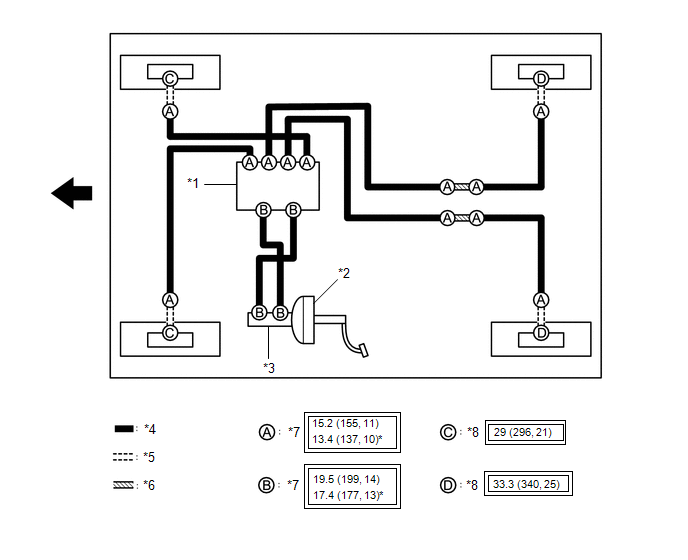
SYSTEM DIAGRAM
HINT:
See the layout drawing to confirm the locations and tightening torque of flexible hoses and brake lines.
|
*1 |
Brake Actuator Assembly |
*2 |
Brake Booster Assembly |
|
*3 |
Brake Master Cylinder Sub-assembly |
*4 |
Brake Tube |
|
*5 |
Flexible Hose |
*6 |
Brake Tube Way |
|
*7 |
Union Nut |
*8 |
Union Bolt |
.png) |
Tightening torque for "Major areas involving basic vehicle performance such as moving/turning/stopping" : N*m (kgf*cm, ft.*lbf) |
* |
For use with a union nut wrench |
.png) |
FRONT |
- |
- |
 Bleeding
BLEEDING
CAUTION / NOTICE / HINT
NOTICE:
Move the shift lever to P and apply the parking brake before bleeding
the brakes.
Add brake fluid to keep the level between the MIN and MAX ...

Other materials:
Toyota CH-R Service Manual > Spiral Cable: Removal
REMOVAL
CAUTION / NOTICE / HINT
The necessary procedures (adjustment, calibration, initialization, or registration)
that must be performed after parts are removed, installed, or replaced during the
spiral cable sub-assembly removal/installation are shown below.
Necessary Procedure After Parts ...
Toyota CH-R Service Manual > Power Window Control System: System Diagram
SYSTEM DIAGRAM
Power Window Control System
Communication Table
Transmitting ECU
Receiving ECU
Signal
Communication Method
Multiplex Network Master Switch Assembly
Power Window Regulator Motor Assembly (for Driver Door)
...
Toyota CH-R Owners Manual
- For safety and security
- Instrument cluster
- Operation of each component
- Driving
- Interior features
- Maintenance and care
- When trouble arises
- Vehicle specifications
- For owners
Toyota CH-R Service Manual
- Introduction
- Maintenance
- Audio / Video
- Cellular Communication
- Navigation / Multi Info Display
- Park Assist / Monitoring
- Brake (front)
- Brake (rear)
- Brake Control / Dynamic Control Systems
- Brake System (other)
- Parking Brake
- Axle And Differential
- Drive Shaft / Propeller Shaft
- K114 Cvt
- 3zr-fae Battery / Charging
- Networking
- Power Distribution
- Power Assist Systems
- Steering Column
- Steering Gear / Linkage
- Alignment / Handling Diagnosis
- Front Suspension
- Rear Suspension
- Tire / Wheel
- Tire Pressure Monitoring
- Door / Hatch
- Exterior Panels / Trim
- Horn
- Lighting (ext)
- Mirror (ext)
- Window / Glass
- Wiper / Washer
- Door Lock
- Heating / Air Conditioning
- Interior Panels / Trim
- Lighting (int)
- Meter / Gauge / Display
- Mirror (int)
- Power Outlets (int)
- Pre-collision
- Seat
- Seat Belt
- Supplemental Restraint Systems
- Theft Deterrent / Keyless Entry

0.0248