Toyota CH-R Service Manual: Steering Angle Sensor
Components
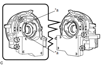
COMPONENTS
ILLUSTRATION

|
*1 |
SPIRAL CABLE SUB-ASSEMBLY |
*2 |
STEERING SENSOR |
Removal
REMOVAL
CAUTION / NOTICE / HINT
The necessary procedures (adjustment, calibration, initialization, or registration) that must be performed after parts are removed, installed, or replaced during the spiral cable with sensor sub-assembly removal/installation are shown below.
Necessary Procedure After Parts Removed/Installed/Replaced|
Replacement Part or Procedure |
Necessary Procedures |
Effects / Inoperative when not performed |
Link |
|---|---|---|---|
|
Disconnect cable from negative battery terminal |
Memorize steering angle neutral point |
Lane departure alert system (w/ Steering Control) |
|
|
Pre-collision system |
|||
|
Initialize back door lock |
Power door lock control system |
|
HINT:
- Use the same procedure for RHD and LHD vehicles.
- The following procedure is for LHD vehicles.
PROCEDURE
1. REMOVE SPIRAL CABLE WITH SENSOR SUB-ASSEMBLY
Click here
.gif)
2. REMOVE STEERING SENSOR
|
(a) Disengage the claws and pins, and remove the spiral cable sub-assembly from the steering sensor. NOTICE: Do not damage the pins of the spiral cable sub-assembly or guides of the steering sensor. |
|
Installation
INSTALLATION
CAUTION / NOTICE / HINT
HINT:
- Use the same procedure for RHD and LHD vehicles.
- The following procedure is for LHD vehicles.
PROCEDURE
1. INSTALL STEERING SENSOR
|
(a) Align the pins and guides, and engage the claws to install the steering sensor to the spiral cable sub-assembly. NOTICE:
|
|

|
(b) Remove the lock pin from the steering sensor. |
|

2. INSTALL SPIRAL CABLE WITH SENSOR SUB-ASSEMBLY
Click here
.gif)
 Rear Speed Sensor
Components
COMPONENTS
ILLUSTRATION
*1
REAR AXLE HUB AND BEARING ASSEMBLY
*2
REAR DISC
*3
REAR DISC BRAKE CALIPER ASSEMBLY ...

Other materials:
Toyota CH-R Service Manual > Rear Combination Light Assembly(for Bulb Type): Reassembly
REASSEMBLY
CAUTION / NOTICE / HINT
HINT:
Use the same procedure for the RH side and LH side.
The following procedure is for the LH side.
PROCEDURE
1. INSTALL REAR COMBINATION LIGHT SOCKET AND WIRE
(a) Connect the connector.
...
Toyota CH-R Service Manual > Axle And Differential: Steering Knuckle
Components
COMPONENTS
ILLUSTRATION
*1
FRONT LOWER BALL JOINT ASSEMBLY
*2
STEERING KNUCKLE
*3
FRONT AXLE HUB SUB-ASSEMBLY
*4
FRONT DISC BRAKE DUST COVER
*5
COTTER PIN
...
Toyota CH-R Owners Manual
- For safety and security
- Instrument cluster
- Operation of each component
- Driving
- Interior features
- Maintenance and care
- When trouble arises
- Vehicle specifications
- For owners
Toyota CH-R Service Manual
- Introduction
- Maintenance
- Audio / Video
- Cellular Communication
- Navigation / Multi Info Display
- Park Assist / Monitoring
- Brake (front)
- Brake (rear)
- Brake Control / Dynamic Control Systems
- Brake System (other)
- Parking Brake
- Axle And Differential
- Drive Shaft / Propeller Shaft
- K114 Cvt
- 3zr-fae Battery / Charging
- Networking
- Power Distribution
- Power Assist Systems
- Steering Column
- Steering Gear / Linkage
- Alignment / Handling Diagnosis
- Front Suspension
- Rear Suspension
- Tire / Wheel
- Tire Pressure Monitoring
- Door / Hatch
- Exterior Panels / Trim
- Horn
- Lighting (ext)
- Mirror (ext)
- Window / Glass
- Wiper / Washer
- Door Lock
- Heating / Air Conditioning
- Interior Panels / Trim
- Lighting (int)
- Meter / Gauge / Display
- Mirror (int)
- Power Outlets (int)
- Pre-collision
- Seat
- Seat Belt
- Supplemental Restraint Systems
- Theft Deterrent / Keyless Entry

0.0206