Toyota CH-R Service Manual: Seat Heater for Front Left Seat does not Operate
DESCRIPTION
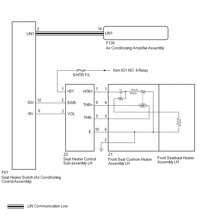
When the seat heater switch on air conditioning control assembly is operated, the seat heater control sub-assembly LH receives the signal. The seat heater control sub-assembly LH receives the signal and operates the front seat heater.
WIRING DIAGRAM
for TMC Made
for TMMT Made

CAUTION / NOTICE / HINT
NOTICE:
- If the battery voltage is low, the seat heater system may not operate.
Refer to Data List for the power steering system.
Click here
.gif)
- Inspect the fuses for circuits related to this system before performing the following procedure.
PROCEDURE
|
1. |
CLEAR DTC |
(a) Clear the DTCs.
Click here
|
.gif)
|
2. |
CHECK FOR DTC |
(a) Check for DTCs.
Click here
OK:
DTC B14B5 is not output.
|
Result |
Proceed to |
|---|---|
|
OK (for TMC Made) |
A |
|
OK (for TMMT Made) |
B |
|
NG |
C |
| B | .gif) |
GO TO STEP 12 |
| C | |
GO TO DIAGNOSTIC TROUBLE CODE CHART |
|
|
3. |
CHECK HARNESS AND CONNECTOR (IG POWER SUPPLY - SEAT HEATER CONTROL SUB-ASSEMBLY LH) |
|
(a) Disconnect the seat heater control sub-assembly LH connector. |
|
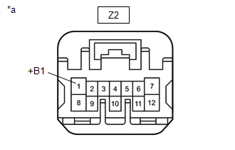
(b) Measure the voltage according to the value(s) in the table below.
Standard Voltage:
|
Tester Connection |
Switch Condition |
Specified Condition |
|---|---|---|
|
Z2-1 (+B1) - Body ground |
Ignition switch ON |
11 to 14 V |
|
Ignition switch off |
Below 1 V |
| NG | |
REPAIR OR REPLACE HARNESS OR CONNECTOR |
|
|
4. |
CHECK HARNESS AND CONNECTOR (SEAT HEATER CONTROL SUB-ASSEMBLY LH - FRONT SEAT CUSHION HEATER ASSEMBLY LH - BODY GROUND) |
(a) Disconnect the Z2 seat heater control sub-assembly LH connector.
(b) Disconnect the Z1 front seat cushion heater assembly LH connector.
(c) Measure the resistance according to the value(s) in the table below.
Standard Resistance:
|
Tester Connection |
Condition |
Specified Condition |
|---|---|---|
|
Z2-7 (HTR1) - Z1-1 |
Always |
Below 1 Ω |
|
Z2-9 (THR+) - Z1-4 |
Always |
Below 1 Ω |
|
Z2-5 (THR-) - Z1-5 |
Always |
Below 1 Ω |
|
Z2-10 (E) - Z1-6 |
Always |
Below 1 Ω |
|
Z1-2 - Body ground |
Always |
Below 1 Ω |
|
Z2-7 (HTR1) or Z1-1 - Body ground |
Always |
10 kΩ or higher |
|
Z2-9 (THR+) or Z1-4 - Body ground |
Always |
10 kΩ or higher |
|
Z2-5 (THR-) or Z1-5 - Body ground |
Always |
10 kΩ or higher |
|
Z2-10 (E) or Z1-6 - Body ground |
Always |
10 kΩ or higher |
| NG | |
REPAIR OR REPLACE HARNESS OR CONNECTOR |
|
|
5. |
INSPECT FRONT SEAT CUSHION HEATER ASSEMBLY LH |
(a) Remove the front seat cushion heater assembly LH.
Click here
(b) Inspect the front seat cushion heater assembly LH.
Click here
| NG | |
REPLACE FRONT SEAT CUSHION HEATER ASSEMBLY LH |
|
|
6. |
INSPECT FRONT SEATBACK HEATER ASSEMBLY LH |
(a) Remove the front seatback heater assembly LH.
Click here
(b) Inspect the front seatback heater assembly LH.
Click here
| NG | |
REPLACE FRONT SEATBACK HEATER ASSEMBLY LH |
|
|
7. |
CHECK HARNESS AND CONNECTOR (SEAT HEATER SWITCH (AIR CONDITIONING CONTROL ASSEMBLY) - SEAT HEATER CONTROL SUB-ASSEMBLY LH) |
(a) Disconnect the F61 seat heater switch (air conditioning control assembly) connector.
(b) Disconnect the Z2 seat heater control sub-assembly LH connector.
(c) Measure the resistance according to the value(s) in the table below.
Standard Resistance:
|
Tester Connection |
Condition |
Specified Condition |
|---|---|---|
|
F61-12 (SW) - Z2-2 (SWR) |
Always |
Below 1 Ω |
|
F61-6 (RV) - Z2-3 (VOL) |
Always |
Below 1 Ω |
|
F61-12 (SW) or Z2-2 (SWR) - Body ground |
Always |
10 kΩ or higher |
|
F61-6 (RV) or Z2-3 (VOL) - Body ground |
Always |
10 kΩ or higher |
| NG | |
REPAIR OR REPLACE HARNESS OR CONNECTOR |
|
|
8. |
REPLACE SEAT HEATER CONTROL SUB-ASSEMBLY LH |
(a) Temporarily replace the heater control sub-assembly LH with a new or known good one.
Click here
|
|
9. |
CHECK SEAT HEATER SYSTEM OPERATION |
(a) Check that the seat heater system is operated normally.
OK:
The seat heater system is operated normally.
| OK | |
END (SEAT HEATER CONTROL SUB-ASSEMBLY LH WAS DEFECTIVE) |
|
|
10. |
REPLACE SEAT HEATER SWITCH (AIR CONDITIONING CONTROL ASSEMBLY) |
(a) Temporarily replace the seat heater switch (air conditioning control assembly) with a new or known good one.
Click here
|
|
11. |
CHECK SEAT HEATER SYSTEM OPERATION |
(a) Check that the seat heater system is operated normally.
OK:
The seat heater system is operated normally.
| OK | |
END (SEAT HEATER SWITCH (AIR CONDITIONING CONTROL ASSEMBLY) WAS DEFECTIVE) |
| NG | |
REPLACE AIR CONDITIONING AMPLIFIER ASSEMBLY |
|
12. |
CHECK HARNESS AND CONNECTOR (IG POWER SUPPLY - SEAT HEATER CONTROL SUB-ASSEMBLY LH) |
|
(a) Disconnect the seat heater control sub-assembly LH connector. |
|

(b) Measure the voltage according to the value(s) in the table below.
Standard Voltage:
|
Tester Connection |
Switch Condition |
Specified Condition |
|---|---|---|
|
Z2-8 (+B1) - Body ground |
Ignition switch ON |
11 to 14 V |
|
Ignition switch off |
Below 1 V |
| NG | |
REPAIR OR REPLACE HARNESS OR CONNECTOR |
|
|
13. |
CHECK HARNESS AND CONNECTOR (SEAT HEATER CONTROL SUB-ASSEMBLY LH - FRONT SEAT CUSHION HEATER ASSEMBLY LH - BODY GROUND) |
(a) Disconnect the Z2 seat heater control sub-assembly LH connector.
(b) Disconnect the Z1 front seat cushion heater assembly LH connector.
(c) Measure the resistance according to the value(s) in the table below.
Standard Resistance:
|
Tester Connection |
Condition |
Specified Condition |
|---|---|---|
|
Z2-1 (HTR1) - Z1-1 |
Always |
Below 1 Ω |
|
Z2-6 (THR+) - Z1-4 |
Always |
Below 1 Ω |
|
Z2-11 (THR-) - Z1-5 |
Always |
Below 1 Ω |
|
Z2-7 (E) - Z1-6 |
Always |
Below 1 Ω |
|
Z1-2 - Body ground |
Always |
Below 1 Ω |
|
Z2-1 (HTR1) or Z1-1 - Body ground |
Always |
10 kΩ or higher |
|
Z2-6 (THR+) or Z1-4 - Body ground |
Always |
10 kΩ or higher |
|
Z2-11 (THR-) or Z1-5 - Body ground |
Always |
10 kΩ or higher |
|
Z2-7 (E) or Z1-6 - Body ground |
Always |
10 kΩ or higher |
| NG | |
REPAIR OR REPLACE HARNESS OR CONNECTOR |
|
|
14. |
INSPECT FRONT SEAT CUSHION HEATER ASSEMBLY LH |
(a) Remove the front seat cushion heater assembly LH.
Click here
(b) Inspect the front seat cushion heater assembly LH.
Click here
| NG | |
REPLACE FRONT SEAT CUSHION HEATER ASSEMBLY LH |
|
|
15. |
INSPECT FRONT SEATBACK HEATER ASSEMBLY LH |
(a) Remove the front seatback heater assembly LH.
Click here
(b) Inspect the front seatback heater assembly LH.
Click here
| NG | |
REPLACE FRONT SEATBACK HEATER ASSEMBLY LH |
|
|
16. |
CHECK HARNESS AND CONNECTOR (SEAT HEATER SWITCH (AIR CONDITIONING CONTROL ASSEMBLY) - SEAT HEATER CONTROL SUB-ASSEMBLY LH) |
(a) Disconnect the F61 seat heater switch (air conditioning control assembly) connector.
(b) Disconnect the Z2 seat heater control sub-assembly LH connector.
(c) Measure the resistance according to the value(s) in the table below.
Standard Resistance:
|
Tester Connection |
Condition |
Specified Condition |
|---|---|---|
|
F61-12 (SW) - Z2-3 (SWR) |
Always |
Below 1 Ω |
|
F61-6 (RV) - Z2-4 (VOL) |
Always |
Below 1 Ω |
|
F61-12 (SW) or Z2-3 (SWR) - Body ground |
Always |
10 kΩ or higher |
|
F61-6 (RV) or Z2-4 (VOL) - Body ground |
Always |
10 kΩ or higher |
| NG | |
REPAIR OR REPLACE HARNESS OR CONNECTOR |
|
|
17. |
REPLACE SEAT HEATER CONTROL SUB-ASSEMBLY LH |
(a) Temporarily replace the heater control sub-assembly LH with a new or known good one.
Click here
|
|
18. |
CHECK SEAT HEATER SYSTEM OPERATION |
(a) Check that the seat heater system is operated normally.
OK:
The seat heater system is operated normally.
| OK | |
END (SEAT HEATER CONTROL SUB-ASSEMBLY LH WAS DEFECTIVE) |
|
|
19. |
REPLACE SEAT HEATER SWITCH (AIR CONDITIONING CONTROL ASSEMBLY) |
(a) Temporarily replace the seat heater switch (air conditioning control assembly) with a new or known good one.
Click here
|
|
20. |
CHECK SEAT HEATER SYSTEM OPERATION |
(a) Check that the seat heater system is operated normally.
OK:
The seat heater system is operated normally.
| OK | |
END (SEAT HEATER SWITCH (AIR CONDITIONING CONTROL ASSEMBLY) WAS DEFECTIVE) |
| NG | |
REPLACE AIR CONDITIONING AMPLIFIER ASSEMBLY |
 Seat Heater for Front Right Seat does not Operate
DESCRIPTION
When the seat heater switch on air conditioning control assembly is operated,
the seat heater control sub-assembly RH receives the signal. The seat heater control
sub-assembly RH rece ...
 Seat Belt
...
Other materials:
Toyota CH-R Service Manual > Rear Console Box: Installation
INSTALLATION
PROCEDURE
1. INSTALL REAR CONSOLE BOX ASSEMBLY
(a) Engage the guides to install the rear console box assembly as shown in the
illustration.
Install in this Direction
(b) Connect the connector.
(c) Install the 4 bolts.
(d) Install the 4 screws.
2. ...
Toyota CH-R Service Manual > Blind Spot Monitor System: Operation Check
OPERATION CHECK
HINT:
The blind spot monitor beam axis confirmation is performed to confirm whether
the sensor's beam axis is correct, and perform adjustment of the beam axis by using
reflector.
BLIND SPOT MONITOR BEAM AXIS CONFIRMATION
(a) When performing the blind spot monitor beam axi ...
Toyota CH-R Owners Manual
- For safety and security
- Instrument cluster
- Operation of each component
- Driving
- Interior features
- Maintenance and care
- When trouble arises
- Vehicle specifications
- For owners
Toyota CH-R Service Manual
- Introduction
- Maintenance
- Audio / Video
- Cellular Communication
- Navigation / Multi Info Display
- Park Assist / Monitoring
- Brake (front)
- Brake (rear)
- Brake Control / Dynamic Control Systems
- Brake System (other)
- Parking Brake
- Axle And Differential
- Drive Shaft / Propeller Shaft
- K114 Cvt
- 3zr-fae Battery / Charging
- Networking
- Power Distribution
- Power Assist Systems
- Steering Column
- Steering Gear / Linkage
- Alignment / Handling Diagnosis
- Front Suspension
- Rear Suspension
- Tire / Wheel
- Tire Pressure Monitoring
- Door / Hatch
- Exterior Panels / Trim
- Horn
- Lighting (ext)
- Mirror (ext)
- Window / Glass
- Wiper / Washer
- Door Lock
- Heating / Air Conditioning
- Interior Panels / Trim
- Lighting (int)
- Meter / Gauge / Display
- Mirror (int)
- Power Outlets (int)
- Pre-collision
- Seat
- Seat Belt
- Supplemental Restraint Systems
- Theft Deterrent / Keyless Entry

0.01