Toyota CH-R Service Manual: Removal
REMOVAL
PROCEDURE
1. REMOVE FRONT DOOR SCUFF PLATE LH
(a) Disengage the claws and guides to remove the front door scuff plate LH as shown in the illustration.

.png) |
Place Hands Here |
.png) |
Remove in this Direction |
2. REMOVE COWL SIDE TRIM BOARD LH
(a) Remove the clip.

|
|
Place Hands Here |
|
|
Remove in this Direction |
(b) Disengage the clips to remove the cowl side trim board LH as shown in the illustration.
3. REMOVE NO. 1 INSTRUMENT PANEL UNDER COVER SUB-ASSEMBLY
(a) Remove the 2 screws.
|
|
Remove in this Direction (1) |
.png) |
Remove in this Direction (2) |
(b) Disengage the claws and guide to remove the No. 1 instrument panel under cover sub-assembly as shown in the illustration.
4. REMOVE INSTRUMENT CLUSTER FINISH PANEL GARNISH ASSEMBLY
(a) Disengage the clips to remove the instrument cluster finish panel garnish assembly as shown in the illustration.

|
|
Remove in this Direction |
5. REMOVE INSTRUMENT PANEL LOWER CENTER FINISH PANEL
(a) Disengage the clips to remove the instrument panel lower center finish panel as shown in the illustration.

|
|
Remove in this Direction |
|
(b) Disengage the claws to disconnect the cooler thermistor. |
|

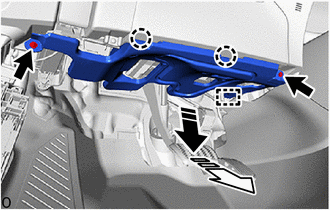
6. REMOVE INSTRUMENT PANEL BOX ASSEMBLY
(a) Disengage the clips and claw to remove the instrument panel box assembly as shown in the illustration.

|
|
Remove in this Direction |
(b) w/ Stereo Jack Adapter:
(1) Disconnect the connector.
7. REMOVE CONSOLE BOX INSERT
(a) Disengage the clips and guide to remove the console box insert as shown in the illustration.

|
|
Remove in this Direction (1) |
|
|
Remove in this Direction (2) |
8. REMOVE NO. 2 FRONT CONSOLE BOX INSERT
(a) Disengage the clips and guide to remove the No. 2 front console box insert as shown in the illustration.

|
|
Remove in this Direction (1) |
|
|
Remove in this Direction (2) |
9. REMOVE SHIFT LEVER KNOB SUB-ASSEMBLY
Click here .gif)
10. REMOVE CONSOLE UPPER PANEL SUB-ASSEMBLY
(a) Disengage the clips to remove the console upper panel sub-assembly as shown in the illustration.

|
|
Remove in this Direction |
(b) Disconnect each connector.
11. REMOVE CONSOLE BOX CUP HOLDER
(a) Disengage the claws to remove the console box cup holder as shown in the illustration.

|
|
Remove in this Direction |
(b) w/ Illumination:
(1) Disconnect the connector.
12. REMOVE NO. 2 CONSOLE BOX CUP HOLDER
(a) Disengage the claws to remove the No. 2 console box cup holder as shown in the illustration.

|
|
Remove in this Direction |
(b) w/ Illumination:
(1) Disconnect the connector.
13. REMOVE CONSOLE BOX CARPET
|
(a) Remove the console box carpet. |
|

14. REMOVE REAR CONSOLE BOX ASSEMBLY
|
(a) Remove the 4 screws. |
|

(b) Remove the 4 bolts.
(c) Disconnect the connector.
(d) Disengage the guides to remove the rear console box assembly as shown in the illustration.

|
|
Remove in this Direction |
 Disassembly
DISASSEMBLY
PROCEDURE
1. REMOVE NO. 1 POWER OUTLET SOCKET ASSEMBLY
Click here
2. REMOVE NO. 1 POWER OUTLET SOCKET COVER
Click here
3. REMOVE CONSOLE REAR END PANEL
(a) Using a moulding remo ...
 Reassembly
REASSEMBLY
PROCEDURE
1. INSTALL CONSOLE COMPARTMENT DOOR SUB-ASSEMBLY
(a) Engage the guides to install the console compartment door sub-assembly.
...
Other materials:
Toyota CH-R Service Manual > Automatic Headlight Beam Level Control System: Height Control Sensor Malfunction (B2416,B241A)
DESCRIPTION
This DTC is stored when the headlight ECU sub-assembly LH detects a malfunction
in the rear height control sensor sub-assembly LH power source circuit or rear height
control sensor sub-assembly LH circuit. The headlight ECU sub-assembly LH stores
DTC B2416 and B241A.
D ...
Toyota CH-R Service Manual > Toyota Entune System: Confirm Cellular Phone Functionality
PROCEDURE
1.
CHECK CUSTOMER'S CELLULAR PHONE COMPATIBILITY
(a) Check if the cellular phone is compatible (Refer to http://www.toyota.com/Entune/).
Result
Proceed to
Cellular phone is compatible.
A
...
Toyota CH-R Owners Manual
- For safety and security
- Instrument cluster
- Operation of each component
- Driving
- Interior features
- Maintenance and care
- When trouble arises
- Vehicle specifications
- For owners
Toyota CH-R Service Manual
- Introduction
- Maintenance
- Audio / Video
- Cellular Communication
- Navigation / Multi Info Display
- Park Assist / Monitoring
- Brake (front)
- Brake (rear)
- Brake Control / Dynamic Control Systems
- Brake System (other)
- Parking Brake
- Axle And Differential
- Drive Shaft / Propeller Shaft
- K114 Cvt
- 3zr-fae Battery / Charging
- Networking
- Power Distribution
- Power Assist Systems
- Steering Column
- Steering Gear / Linkage
- Alignment / Handling Diagnosis
- Front Suspension
- Rear Suspension
- Tire / Wheel
- Tire Pressure Monitoring
- Door / Hatch
- Exterior Panels / Trim
- Horn
- Lighting (ext)
- Mirror (ext)
- Window / Glass
- Wiper / Washer
- Door Lock
- Heating / Air Conditioning
- Interior Panels / Trim
- Lighting (int)
- Meter / Gauge / Display
- Mirror (int)
- Power Outlets (int)
- Pre-collision
- Seat
- Seat Belt
- Supplemental Restraint Systems
- Theft Deterrent / Keyless Entry

0.0178