Toyota CH-R Service Manual: Components
COMPONENTS
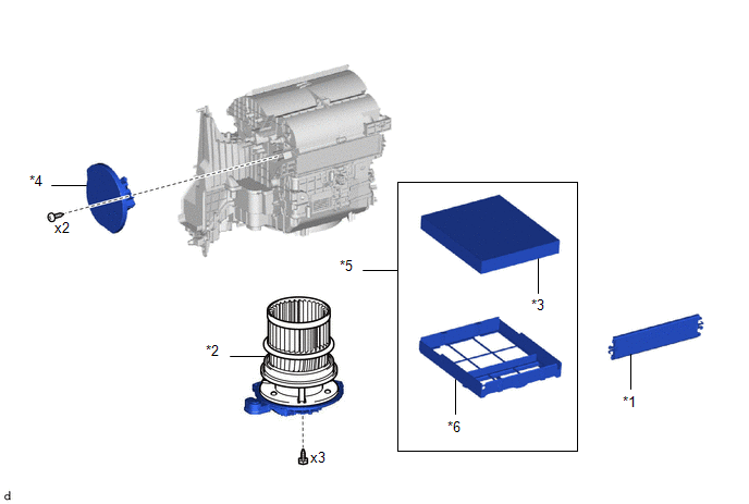
ILLUSTRATION

|
*1 |
BLOWER ASSEMBLY |
*2 |
NO. 2 AIR DUCT |
|
● |
Non-reusable part |
- |
- |
ILLUSTRATION
|
*1 |
AIR FILTER COVER PLATE |
*2 |
BLOWER MOTOR WITH FAN SUB-ASSEMBLY |
|
*3 |
CLEAN AIR FILTER |
*4 |
NO. 1 BLOWER DAMPER SERVO SUB-ASSEMBLY |
|
*5 |
AIR FILTER COVER PLATE |
*6 |
COOLING UNIT PARTS |

 Disassembly
DISASSEMBLY
PROCEDURE
1. PRECAUTION
NOTICE:
Make sure to perform initialization after replacing the No. 1 blower damper servo
sub-assembly. If initialization is not performed, the air conditione ...
Other materials:
Toyota CH-R Service Manual > Airbag System: Front Door Pressure Sensor LH (B167A/5A,B167E/5A)
DESCRIPTION
The side collision sensor LH circuit (bus 1) consists of the airbag sensor assembly,
door side airbag sensor LH, No. 1 side airbag sensor LH and No. 2 side airbag sensor
LH.
The door side airbag sensor LH, No. 1 side airbag sensor LH and No. 2 side airbag
sensor LH detect impacts ...
Toyota CH-R Service Manual > Can Communication System: Diagnostic Trouble Code Chart
DIAGNOSTIC TROUBLE CODE CHART
Diagnostic Trouble Code Chart
DTC No.
Detection Item
Trouble Area
Link
B1003
ECU Malfunction
Central gateway ECU (network gateway ECU)
...
Toyota CH-R Owners Manual
- For safety and security
- Instrument cluster
- Operation of each component
- Driving
- Interior features
- Maintenance and care
- When trouble arises
- Vehicle specifications
- For owners
Toyota CH-R Service Manual
- Introduction
- Maintenance
- Audio / Video
- Cellular Communication
- Navigation / Multi Info Display
- Park Assist / Monitoring
- Brake (front)
- Brake (rear)
- Brake Control / Dynamic Control Systems
- Brake System (other)
- Parking Brake
- Axle And Differential
- Drive Shaft / Propeller Shaft
- K114 Cvt
- 3zr-fae Battery / Charging
- Networking
- Power Distribution
- Power Assist Systems
- Steering Column
- Steering Gear / Linkage
- Alignment / Handling Diagnosis
- Front Suspension
- Rear Suspension
- Tire / Wheel
- Tire Pressure Monitoring
- Door / Hatch
- Exterior Panels / Trim
- Horn
- Lighting (ext)
- Mirror (ext)
- Window / Glass
- Wiper / Washer
- Door Lock
- Heating / Air Conditioning
- Interior Panels / Trim
- Lighting (int)
- Meter / Gauge / Display
- Mirror (int)
- Power Outlets (int)
- Pre-collision
- Seat
- Seat Belt
- Supplemental Restraint Systems
- Theft Deterrent / Keyless Entry

0.0085