Toyota CH-R Service Manual: Parts Location
PARTS LOCATION
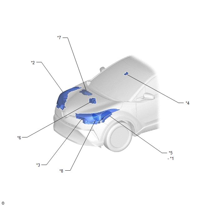
ILLUSTRATION
|
*1 |
NO. 1 INTEGRATION RELAY - H-LP RH RELAY - H-LP LH RELAY |
*2 |
HEADLIGHT UNIT ASSEMBLY RH |
|
*3 |
HEADLIGHT UNIT ASSEMBLY LH |
*4 |
FORWARD RECOGNITION CAMERA |
|
*5 |
NO. 1 ENGINE ROOM RELAY BLOCK - H-LP RH FUSE - H-LP LH FUSE - H-LP SHADE FUSE |
*6 |
BRAKE ACTUATOR ASSEMBLY (SKID CONTROL ECU) |
|
*7 |
NO. 2 ENGINE ROOM RELAY BLOCK - H-LP SHADE RELAY |
*8 |
ECM |
ILLUSTRATION

|
*1 |
AUTOMATIC LIGHT CONTROL SENSOR |
*2 |
HEADLIGHT DIMMER SWITCH ASSEMBLY |
|
*3 |
AUTO HIGH BEAM SWITCH |
*4 |
COMBINATION METER ASSEMBLY |
|
*5 |
AIRBAG ECU ASSEMBLY (YAW RATE SENSOR) |
*6 |
DLC3 |
|
*7 |
MAIN BODY ECU (MULTIPLEX NETWORK BODY ECU) |
*8 |
INSTRUMENT PANEL JUNCTION BLOCK ASSEMBLY - ECU-IG1 NO. 4 FUSE |
 Precaution
PRECAUTION
IGNITION SWITCH EXPRESSIONS
(a) The type of ignition switch used on this model differs depending on the specifications
of the vehicle. The expressions listed in the table below are used ...
 System Description
SYSTEM DESCRIPTION
AUTOMATIC HIGH BEAM SYSTEM
(a) General
The automatic high beam system enhances the illumination of the area in front
of the vehicle to improve visibility for the driver. It wor ...
Other materials:
Toyota CH-R Service Manual > Meter / Gauge System: Entire Combination Meter does not Operate
DESCRIPTION
This circuit is the power source circuit for the combination meter assembly.
This circuit provides two types of power sources; one is a constant power source,
and the other is an IG power source.
WIRING DIAGRAM
CAUTION / NOTICE / HINT
NOTICE:
Inspect the fuses of circu ...
Toyota CH-R Service Manual > Air Conditioning System(for Automatic Air Conditioning System With Side-mounted
Air Conditioner Pressure Sensor): Back-up Power Source Circuit
DESCRIPTION
The back-up power source circuit for the air conditioning amplifier assembly
is shown below. Power is supplied even when the ignition switch is off. This power
is used for diagnostic trouble code memory, etc.
WIRING DIAGRAM
CAUTION / NOTICE / HINT
NOTICE:
Inspect the fuses for ...
Toyota CH-R Owners Manual
- For safety and security
- Instrument cluster
- Operation of each component
- Driving
- Interior features
- Maintenance and care
- When trouble arises
- Vehicle specifications
- For owners
Toyota CH-R Service Manual
- Introduction
- Maintenance
- Audio / Video
- Cellular Communication
- Navigation / Multi Info Display
- Park Assist / Monitoring
- Brake (front)
- Brake (rear)
- Brake Control / Dynamic Control Systems
- Brake System (other)
- Parking Brake
- Axle And Differential
- Drive Shaft / Propeller Shaft
- K114 Cvt
- 3zr-fae Battery / Charging
- Networking
- Power Distribution
- Power Assist Systems
- Steering Column
- Steering Gear / Linkage
- Alignment / Handling Diagnosis
- Front Suspension
- Rear Suspension
- Tire / Wheel
- Tire Pressure Monitoring
- Door / Hatch
- Exterior Panels / Trim
- Horn
- Lighting (ext)
- Mirror (ext)
- Window / Glass
- Wiper / Washer
- Door Lock
- Heating / Air Conditioning
- Interior Panels / Trim
- Lighting (int)
- Meter / Gauge / Display
- Mirror (int)
- Power Outlets (int)
- Pre-collision
- Seat
- Seat Belt
- Supplemental Restraint Systems
- Theft Deterrent / Keyless Entry

0.0199