Toyota CH-R Service Manual: Removal
REMOVAL
CAUTION / NOTICE / HINT
The necessary procedures (adjustment, calibration, initialization, or registration) that must be performed after parts are removed and installed, or replaced during steering gear assembly removal/installation are shown below.
Necessary Procedures After Parts Removed/Installed/Replaced|
Replaced Part or Performed Procedure |
Necessary Procedure |
Effect/Inoperative Function when Necessary Procedure not Performed |
Link |
|---|---|---|---|
|
Front wheel alignment adjustment |
|
|
|
PROCEDURE
1. ALIGN FRONT WHEELS FACING STRAIGHT AHEAD
2. SECURE STEERING WHEEL ASSEMBLY
|
(a) Secure the steering wheel with the seat belt in order to prevent rotation. HINT: This operation is useful to prevent damage to the spiral cable. |
|

3. REMOVE COLUMN HOLE COVER SILENCER SHEET
Click here
.gif)
4. SEPARATE NO. 2 STEERING INTERMEDIATE SHAFT ASSEMBLY
Click here
5. SEPARATE NO. 1 STEERING COLUMN HOLE COVER SUB-ASSEMBLY
|
(a) Separate the clip (A), disengage the clip (B) from the vehicle body and separate the No. 1 steering column hole cover sub-assembly. NOTICE: Do not damage the clips (A) or (B). |
|

6. REMOVE FRONT WHEELS
Click here
7. SEPARATE TIE ROD END SUB-ASSEMBLY LH
|
(a) Remove the cotter pin and nut. |
|

|
(b) Install SST to the tie rod end sub-assembly LH. SST: 09960-20010 09961-02060 NOTICE: Make sure that the upper ends of the tie rod end sub-assembly LH and SST are aligned. |
|

(c) Secure SST using a string.
NOTICE:
Be sure to tighten the string firmly to secure SST to the steering knuckle LH to prevent SST from falling off.
(d) Using SST, separate the tie rod end sub-assembly LH from the steering knuckle LH.
SST: 09960-20010
09961-02010

|
*a |
String |
*b |
Molybdenum Grease Application Area |
|
*c |
Place wrench here |
*d |
Center Nut |
.png) |
Turn |
- |
- |
CAUTION:
Apply molybdenum grease to the bolt threads and the tip of SST.
NOTICE:
- Be sure to tighten the string firmly to secure SST to the steering knuckle LH to prevent SST from falling off.
- Install SST with the center nut so that (A) and (B) shown in the illustration are parallel. Otherwise, the ball joint dust cover may be damaged.
- Be sure to place the wrench on the part shown in the illustration.
- Do not damage the front disc brake dust cover.
- Do not damage the ball joint dust cover.
- Do not damage the steering knuckle LH.
8. SEPARATE TIE ROD END SUB-ASSEMBLY RH
HINT:
Perform the same procedure as for the LH side.
9. REMOVE STEERING LINK ASSEMBLY
|
(a) Disconnect the connector. |
|
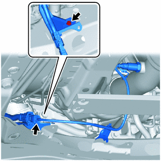
(b) Remove the bolt and separate the wire harness clamp bracket from the front suspension crossmember sub-assembly.
|
(c) Remove the 2 bolts, 2 nuts and steering link assembly from the front suspension crossmember sub-assembly. NOTICE: Because the nut has its own stopper, do not turn the nut. Loosen the bolt with the nut secured. |
|

|
(d) Remove the No. 1 steering column hole cover sub-assembly from the steering link assembly. |
|

(e) Remove the steering link assembly as shown in the illustration.

|
|
Remove in this Direction |
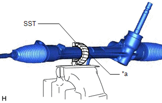
10. SECURE STEERING LINK ASSEMBLY
|
(a) Using SST, secure the steering link assembly in a vise. SST: 09612-00012 HINT: Wrap SST with protective tape before use. |
|
11. REMOVE TIE ROD END SUB-ASSEMBLY LH
|
(a) Put matchmarks on the tie rod end sub-assembly LH and steering gear assembly. |
|

(b) Remove the tie rod end sub-assembly LH and lock nut.
12. REMOVE TIE ROD END SUB-ASSEMBLY RH
HINT:
Perform the same procedure as for the LH side.
 Components
COMPONENTS
ILLUSTRATION
*1
NO. 1 STEERING COLUMN HOLE COVER SUB-ASSEMBLY
*2
NO. 2 STEERING INTERMEDIATE SHAFT ASSEMBLY
*3
ST ...
 Disassembly
DISASSEMBLY
PROCEDURE
1. REMOVE STEERING RACK BOOT CLIP (for LH Side)
(a) Using pliers, remove the steering rack boot clip.
2. REMOVE STEERING RACK BOOT CLIP (for RH Side)
HINT:
Perform the same ...
Other materials:
Toyota CH-R Service Manual > Air Conditioning System(for Automatic Air Conditioning System With Top-mounted
Air Conditioner Pressure Sensor): Back-up Power Source Circuit
DESCRIPTION
The back-up power source circuit for the air conditioning amplifier assembly
is shown below. Power is supplied even when the ignition switch is off. This power
is used for diagnostic trouble code memory, etc.
WIRING DIAGRAM
CAUTION / NOTICE / HINT
NOTICE:
Inspect the fuses for ...
Toyota CH-R Service Manual > Theft Deterrent System: Power Source Circuit
DESCRIPTION
Based on changes in the power source voltage, the main body ECU (multiplex network
body ECU) can detect if the battery has been disconnected and reconnected.
WIRING DIAGRAM
CAUTION / NOTICE / HINT
NOTICE:
Before replacing the main body ECU (multiplex network body ECU), r ...
Toyota CH-R Owners Manual
- For safety and security
- Instrument cluster
- Operation of each component
- Driving
- Interior features
- Maintenance and care
- When trouble arises
- Vehicle specifications
- For owners
Toyota CH-R Service Manual
- Introduction
- Maintenance
- Audio / Video
- Cellular Communication
- Navigation / Multi Info Display
- Park Assist / Monitoring
- Brake (front)
- Brake (rear)
- Brake Control / Dynamic Control Systems
- Brake System (other)
- Parking Brake
- Axle And Differential
- Drive Shaft / Propeller Shaft
- K114 Cvt
- 3zr-fae Battery / Charging
- Networking
- Power Distribution
- Power Assist Systems
- Steering Column
- Steering Gear / Linkage
- Alignment / Handling Diagnosis
- Front Suspension
- Rear Suspension
- Tire / Wheel
- Tire Pressure Monitoring
- Door / Hatch
- Exterior Panels / Trim
- Horn
- Lighting (ext)
- Mirror (ext)
- Window / Glass
- Wiper / Washer
- Door Lock
- Heating / Air Conditioning
- Interior Panels / Trim
- Lighting (int)
- Meter / Gauge / Display
- Mirror (int)
- Power Outlets (int)
- Pre-collision
- Seat
- Seat Belt
- Supplemental Restraint Systems
- Theft Deterrent / Keyless Entry

0.011