Toyota CH-R Service Manual: Torque Sensor1 (C1511-C1514,C1517)
DESCRIPTION
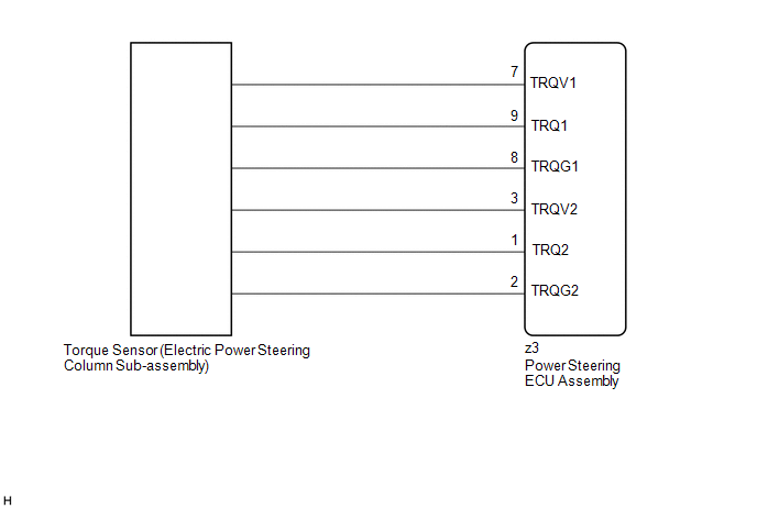
The torque sensor converts the rotational torque received from the steering wheel into electric signals and sends them to the power steering ECU assembly.
|
DTC No. |
Detection Item |
DTC Detection Condition |
Trouble Area |
Warning Indicate |
Return-to-normal Condition |
Note |
|---|---|---|---|---|---|---|
|
C1511 |
Torque Sensor1 |
Torque sensor malfunction |
|
EPS warning light: Comes on |
The ECU judges the system has returned to normal or the ignition switch ON again |
- |
|
C1512 |
Torque Sensor2 |
Torque sensor malfunction |
|
EPS warning light: Comes on |
The ECU judges the system has returned to normal or the ignition switch ON again |
- |
|
C1513 |
Torque Sensor Deviation Excessive |
Torque sensor malfunction |
|
EPS warning light: Comes on |
The ECU judges the system has returned to normal or the ignition switch ON again |
- |
|
C1514 |
Torque Sensor Power Supply Voltage |
Torque sensor malfunction |
|
EPS warning light: Comes on |
Ignition switch ON again |
- |
|
C1517 |
Torque Hold |
Torque sensor malfunction |
|
EPS warning light: Comes on |
Ignition switch ON again |
- |
WIRING DIAGRAM
CAUTION / NOTICE / HINT
NOTICE:
- If the electric power steering column sub-assembly has been replaced,
perform torque sensor zero point calibration.
Click here
.gif)
- If the power steering ECU assembly has been replaced, perform assist
map writing and torque sensor zero point calibration.
Click here
PROCEDURE
|
1. |
CHECK CONNECTOR CONNECTION CONDITION |
(a) Check the connection condition of the torque sensor connector.
OK:
Torque sensor connector is securely connected to the power steering ECU assembly.
| NG | .gif) |
CONNECT CONNECTOR |
|
.gif)
|
2. |
CHECK POWER STEERING ECU ASSEMBLY (TRQV VOLTAGE) |
|
(a) Turn the ignition switch to ON. |
|

(b) Measure the voltage according to the value(s) in the table below.
Standard Voltage:
|
Tester Connection |
Condition |
Specified Condition |
|---|---|---|
|
z3-7 (TRQV1) - z3-8 (TRQG1) |
Ignition switch ON |
4.5 to 5.5 V |
|
z3-3 (TRQV2) - z3-2 (TRQG2) |
Ignition switch ON |
4.5 to 5.5 V |
| NG | |
REPLACE POWER STEERING ECU ASSEMBLY |
|
|
3. |
CHECK POWER STEERING ECU ASSEMBLY (TRQ1, TRQ2 VOLTAGE) |
|
(a) Turn the engine running. |
|

(b) Measure the voltage according to the value(s) in the table below.
Standard Voltage:
|
Tester Connection |
Condition |
Specified Condition |
|---|---|---|
|
z3-9 (TRQ1) - z3-8 (TRQG1) |
Engine running and steering wheel not being turned (without load) |
2.3 to 2.7 V |
|
Engine running and steering wheel being turned to the right with vehicle stopped |
2.5 to 3.8 V |
|
|
Engine running and steering wheel being turned to the left with vehicle stopped |
1.2 to 2.5 V |
|
|
z3-1 (TRQ2) - z3-2 (TRQG2) |
Engine running and steering wheel not being turned (without load) |
2.3 to 2.7 V |
|
Engine running and steering wheel being turned to the right with vehicle stopped |
1.2 to 2.5 V |
|
|
Engine running and steering wheel being turned to the left with vehicle stopped |
2.5 to 3.8 V |
(c) Under each condition, measure the voltage at terminals TRQ1 and TRQ2, and calculate the sum.
Standard Voltage:
|
Tester Connection |
Condition |
Specified Condition |
|---|---|---|
|
Sum of voltage between z3-9 (TRQ1) and z3-8 (TRQG1) and voltage between z3-1 (TRQ2) and z3-2 (TRQG2) |
Engine running and steering wheel not being turned (without load) |
Between 4.75 V and 5.25 V |
|
Engine running and steering wheel being turned to the right with vehicle stopped |
||
|
Engine running and steering wheel being turned to the left with vehicle stopped |
| OK | |
REPLACE POWER STEERING ECU ASSEMBLY |
| NG | |
REPLACE ELECTRIC POWER STEERING COLUMN SUB-ASSEMBLY |
 PIG Power Supply Voltage (C1552,C1554)
DESCRIPTION
If a problem occurs in the system, the power source relay circuit and the motor
relay circuit are shut off to stop power assist. The ECU must be replaced when there
is a problem with ...
 Torque Sensor Zero Point Adjustment Undone (C1515)
DESCRIPTION
This DTC does not indicate a malfunction. The power steering ECU assembly stores
this DTC when it determines that torque sensor zero point calibration has not been
performed.
...
Other materials:
Toyota CH-R Service Manual > Can Communication System: Radio Receiver Assembly Communication Stop Mode
DESCRIPTION
Detection Item
Symptom
Trouble Area
Radio Receiver Assembly Communication Stop Mode
Any of the following conditions are met:
Communication stop for "Display and Navigation (AVN)" is indicated
on t ...
Toyota CH-R Service Manual > Stop Light Switch: On-vehicle Inspection
ON-VEHICLE INSPECTION
PROCEDURE
1. INSPECT STOP LIGHT SWITCH ASSEMBLY
(a) Disconnect the A45 stop light switch assembly connector.
*a
Front view of wire harness connector
(to Stop Li ...
Toyota CH-R Owners Manual
- For safety and security
- Instrument cluster
- Operation of each component
- Driving
- Interior features
- Maintenance and care
- When trouble arises
- Vehicle specifications
- For owners
Toyota CH-R Service Manual
- Introduction
- Maintenance
- Audio / Video
- Cellular Communication
- Navigation / Multi Info Display
- Park Assist / Monitoring
- Brake (front)
- Brake (rear)
- Brake Control / Dynamic Control Systems
- Brake System (other)
- Parking Brake
- Axle And Differential
- Drive Shaft / Propeller Shaft
- K114 Cvt
- 3zr-fae Battery / Charging
- Networking
- Power Distribution
- Power Assist Systems
- Steering Column
- Steering Gear / Linkage
- Alignment / Handling Diagnosis
- Front Suspension
- Rear Suspension
- Tire / Wheel
- Tire Pressure Monitoring
- Door / Hatch
- Exterior Panels / Trim
- Horn
- Lighting (ext)
- Mirror (ext)
- Window / Glass
- Wiper / Washer
- Door Lock
- Heating / Air Conditioning
- Interior Panels / Trim
- Lighting (int)
- Meter / Gauge / Display
- Mirror (int)
- Power Outlets (int)
- Pre-collision
- Seat
- Seat Belt
- Supplemental Restraint Systems
- Theft Deterrent / Keyless Entry

0.0093